


Appendix D: Specifications
D–4
CTS 710 SONET Test Set User Manual
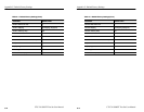
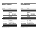
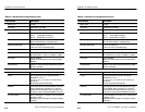
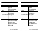
Table D–1: Standard CTS 710 Specifications (Cont.)
Characteristic Description
Return Loss >15 dB
Connector
Unbalanced, 75 W BNC
Optical Input
Data Rates OC-1: 51.84 Mb/s (±100 ppm)
OC-3: 155.52 Mb/s (±100 ppm)
OC-12: 622.08 Mb/s (±100 ppm)
Maximum Input Power –7 dBm:
Opt. 05 and 06 include a 10 dB attenuator
Operating Wavelength 1310 nm and 1550 nm:
1100 nm to 1570 nm operating range
Signal Sensitivity –28 dBm for BER ≤10
–10
Optical Power Meter Accuracy 2 dBm, Typical:
For input power in a range of –30 dBm to –6 dBm
Connectors FC-PC standard:
Optical connector kit with ST, SC, and DIN 27256
included
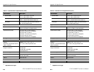
Through Mode Monitors a selected channel and passes the signal
through unchanged
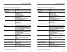
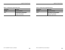
Transmit and Receive Functional Specifications
Transport Overhead
Access Set overhead bytes to any value from binary
00000000 to 11111111:
A1, A2, C1, E1, F1, D1–D3, K1, K2, D4–D12, S1,
Z2, M2, E2
View all Transport Overhead bytes
Add/Drop Insert data from the Overhead Add/Drop connector
into the Section DCC, Line DCC or F1 user byte.
Drops data from the Section DCC, Line DCC, or F1
user byte out to the Overhead Add/Drop connector.
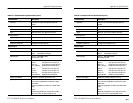
K1 and K2 (APS) Set the APS Bytes, K1 and K2, to any code defined
in ANSI T1.105A
Selectable by text description for all Span and Ring
messages
Appendix D: Specifications
D–4
CTS 710 SONET Test Set User Manual
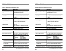
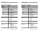
Table D–1: Standard CTS 710 Specifications (Cont.)
Characteristic Description
Return Loss >15 dB
Connector
Unbalanced, 75 W BNC
Optical Input
Data Rates OC-1: 51.84 Mb/s (±100 ppm)
OC-3: 155.52 Mb/s (±100 ppm)
OC-12: 622.08 Mb/s (±100 ppm)
Maximum Input Power –7 dBm:
Opt. 05 and 06 include a 10 dB attenuator
Operating Wavelength 1310 nm and 1550 nm:
1100 nm to 1570 nm operating range
Signal Sensitivity –28 dBm for BER ≤10
–10
Optical Power Meter Accuracy 2 dBm, Typical:
For input power in a range of –30 dBm to –6 dBm
Connectors FC-PC standard:
Optical connector kit with ST, SC, and DIN 27256
included
Through Mode Monitors a selected channel and passes the signal
through unchanged
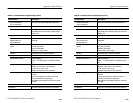
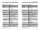
Transmit and Receive Functional Specifications
Transport Overhead
Access Set overhead bytes to any value from binary
00000000 to 11111111:
A1, A2, C1, E1, F1, D1–D3, K1, K2, D4–D12, S1,
Z2, M2, E2
View all Transport Overhead bytes
Add/Drop Insert data from the Overhead Add/Drop connector
into the Section DCC, Line DCC or F1 user byte.
Drops data from the Section DCC, Line DCC, or F1
user byte out to the Overhead Add/Drop connector.
K1 and K2 (APS) Set the APS Bytes, K1 and K2, to any code defined
in ANSI T1.105A
Selectable by text description for all Span and Ring
messages