


Appendix D: Specifications
D–8
CTS 710 SONET Test Set User Manual
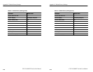
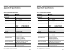
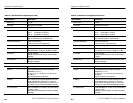
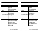
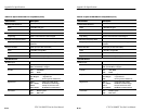
Table D–1: Standard CTS 710 Specifications (Cont.)
Characteristic Description
AutoScan AutoScan to incoming signal (rate, mapping,
framing, and pattern).
Identifies incoming signal and presents graphical
display of SPE and VT structure.
Identifies VT signal status by showing VT number,
equipped vs unequipped, alarms and pattern.
Stored Setups 5 front panel setups in memory
200 front panel setups per disk
Pass/Fail Tests Predefined Pass/Fail Tests can be created, stored
and executed
Pass/Fail tests are stored on disk
200 Pass/Fail test setups per disk
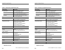
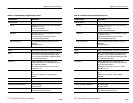
Add/Drop Interface for
Data Communication Channels and
User Channels
A DB-37 female connector provides the interface to
an external protocol analyzer.
Clock and data signals are differential TTL, conform
to RS-422 specifications, and are also compatible
with single-ended TTL signals.
Add/Drop: D1–D3, D4–D12, F1, F2
Connector: 37 Pin DIN (DTE and DCE)
Triggering Pulse at start of each frame, (Tx and Rx),
Connector: 37 Pin DIN
Disk Drive 3.5 inch, 1.44 MB, DOS compatible
Measurement Result stored in ASCII
Stored Setups and Pass/Fail Tests in IEEE 488.2
format
Printer Optional printer in pouch (thermal): HC 411
Printer support: Epson, HP Thinkjet
Serial Printer Port: RS-232
Print to disk: BMP format, Interleaf format, and
Encapsulated PostScript
Computer Interface IEEE-488.2 interface
RS-232-C interface (DB9)
Appendix D: Specifications
D–8
CTS 710 SONET Test Set User Manual
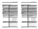
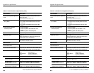
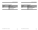
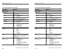
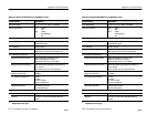
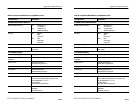
Table D–1: Standard CTS 710 Specifications (Cont.)
Characteristic Description
AutoScan AutoScan to incoming signal (rate, mapping,
framing, and pattern).
Identifies incoming signal and presents graphical
display of SPE and VT structure.
Identifies VT signal status by showing VT number,
equipped vs unequipped, alarms and pattern.
Stored Setups 5 front panel setups in memory
200 front panel setups per disk
Pass/Fail Tests Predefined Pass/Fail Tests can be created, stored
and executed
Pass/Fail tests are stored on disk
200 Pass/Fail test setups per disk
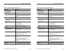
Add/Drop Interface for
Data Communication Channels and
User Channels
A DB-37 female connector provides the interface to
an external protocol analyzer.
Clock and data signals are differential TTL, conform
to RS-422 specifications, and are also compatible
with single-ended TTL signals.
Add/Drop: D1–D3, D4–D12, F1, F2
Connector: 37 Pin DIN (DTE and DCE)
Triggering Pulse at start of each frame, (Tx and Rx),
Connector: 37 Pin DIN
Disk Drive 3.5 inch, 1.44 MB, DOS compatible
Measurement Result stored in ASCII
Stored Setups and Pass/Fail Tests in IEEE 488.2
format
Printer Optional printer in pouch (thermal): HC 411
Printer support: Epson, HP Thinkjet
Serial Printer Port: RS-232
Print to disk: BMP format, Interleaf format, and
Encapsulated PostScript
Computer Interface IEEE-488.2 interface
RS-232-C interface (DB9)