


Appendix G: Rear-Panel Connectors
CTS 710 SONET Test Set User Manual
G–5
Overhead Add/Drop Port
You use the Overhead Add/Drop port to add/drop the section and line
data communication channels (DCC), and the section and line user
channels. The DCC and user channel add/drop functions are
independent; for example, you can add a DCC while dropping a user
channel. Only one DCC or user channel can be added or dropped at a
time. The parameters for adding a DCC or a user channel are located
on the TRANSPORT OVERHEAD and PATH OVERHEAD pages of
the TRANSMIT menu. The parameters for dropping a DCC or a user
channel are located on the TRANSPORT OVERHEAD and PATH
OVERHEAD pages of the RECEIVE menu.
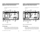
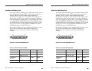
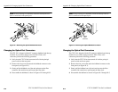
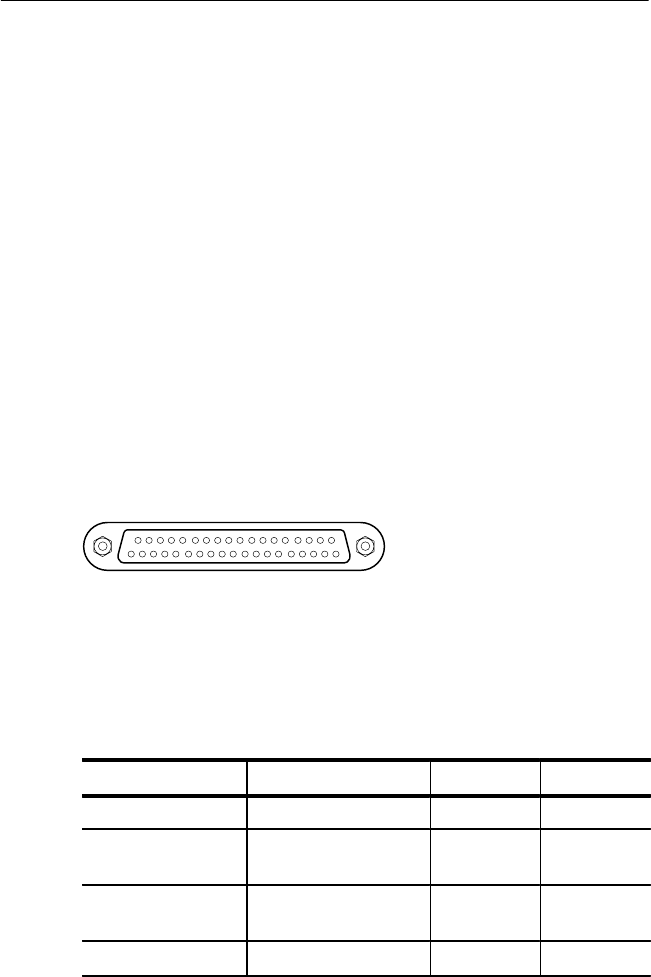
The Overhead Add/Drop port uses a gapped clock. Figure G–4 shows
how the pins are numbered on the Overhead Add/Drop port.
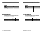
Tables G–3 and G–4 summarize the different communication
channels.
119
20 37
Figure G–4: The Overhead Add/Drop Port
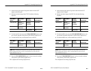
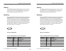
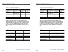
Table G–3: Overhead Channels Added
Added Channel Bytes Added Data Rate Clock Rate
Section DCC D1, D2, D3 192 kbps 216 kHz
Line DCC D4, D5, D6, D7, D8,
D9, D10, D11, D12
576 kbps 2.16 MHz
1
Section User
Channel
F1 64 kbps 72 kHz
Path User Channel F2 64 kbps 72 kHz
1
The Line DCC signal has a 1/3–2/3 duty ratio.
Appendix G: Rear-Panel Connectors
CTS 710 SONET Test Set User Manual
G–5
Overhead Add/Drop Port
You use the Overhead Add/Drop port to add/drop the section and line
data communication channels (DCC), and the section and line user
channels. The DCC and user channel add/drop functions are
independent; for example, you can add a DCC while dropping a user
channel. Only one DCC or user channel can be added or dropped at a
time. The parameters for adding a DCC or a user channel are located
on the TRANSPORT OVERHEAD and PATH OVERHEAD pages of
the TRANSMIT menu. The parameters for dropping a DCC or a user
channel are located on the TRANSPORT OVERHEAD and PATH
OVERHEAD pages of the RECEIVE menu.
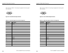
The Overhead Add/Drop port uses a gapped clock. Figure G–4 shows
how the pins are numbered on the Overhead Add/Drop port.
Tables G–3 and G–4 summarize the different communication
channels.
119
20 37
Figure G–4: The Overhead Add/Drop Port
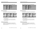
Table G–3: Overhead Channels Added
Added Channel Bytes Added Data Rate Clock Rate
Section DCC D1, D2, D3 192 kbps 216 kHz
Line DCC D4, D5, D6, D7, D8,
D9, D10, D11, D12
576 kbps 2.16 MHz
1
Section User
Channel
F1 64 kbps 72 kHz
Path User Channel F2 64 kbps 72 kHz
1
The Line DCC signal has a 1/3–2/3 duty ratio.