


Appendix E: Incoming Inspection Test
CTS 710 SONET Test Set User Manual
E–3
How to Proceed
If the CTS 710 fails any of these tests, it has failed the incoming
inspection test. Double check the electrical and optical connections
and repeat any failed test. If the failure persists, contact your local
Tektronix field office or representative for assistance.
You can perform the following tests in any order. Each test is
independent and does not depend on the setup from the previous test.
H Turn on the CTS 710. Allow it to warm up for 20 minutes before
proceeding with the tests.
System Self Test with External Loop-Back
This test executes the Self Test including coverage of the transmitter
and receiver I/O circuitry.
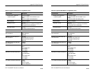
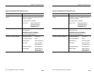
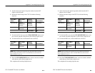
Equipment
Required
75 W BNC coaxial cable for electrical loop-back
Optical loop-back cable if Electrical/Optical Plug-in
Interface Module is installed
Prerequisites CTS 710 warmed-up at least twenty minutes
Time Required
Approximately two minutes
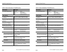
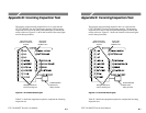
1. Attach electrical and optical loop-back cables from the
TRANSMIT/OUT outputs to the RECEIVE/IN inputs.
NOTE. Connectors labeled OUT and IN are present only on
instruments equipped with the Add/Drop/Test Option.
Appendix E: Incoming Inspection Test
CTS 710 SONET Test Set User Manual
E–3
How to Proceed
If the CTS 710 fails any of these tests, it has failed the incoming
inspection test. Double check the electrical and optical connections
and repeat any failed test. If the failure persists, contact your local
Tektronix field office or representative for assistance.
You can perform the following tests in any order. Each test is
independent and does not depend on the setup from the previous test.
H Turn on the CTS 710. Allow it to warm up for 20 minutes before
proceeding with the tests.
System Self Test with External Loop-Back
This test executes the Self Test including coverage of the transmitter
and receiver I/O circuitry.
Equipment
Required
75 W BNC coaxial cable for electrical loop-back
Optical loop-back cable if Electrical/Optical Plug-in
Interface Module is installed
Prerequisites CTS 710 warmed-up at least twenty minutes
Time Required
Approximately two minutes
1. Attach electrical and optical loop-back cables from the
TRANSMIT/OUT outputs to the RECEIVE/IN inputs.
NOTE. Connectors labeled OUT and IN are present only on
instruments equipped with the Add/Drop/Test Option.