


Appendix G: Rear-Panel Connectors
CTS 710 SONET Test Set User Manual
G–3
GPIB Port
The GPIB (General Purpose Interface Bus) port is used for remote
control of the CTS 710. For detailed information on remote control
of the CTS 710, see the CTS 710 SONET Test Set Programmer
Manual (Tektronix part number 070-8924-XX)
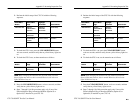
RS-232 Port
The rear panel RS-232 connector is used to connect to printers and
instrument controllers. Set the RS-232 parameters for printers on the
PRINTER SETUP page of the UTILITY menu. Set the RS-232
parameters for instrument controllers on the REMOTE CONTROL
page of the UTILITY menu. You can find more detailed information
on remote control of the CTS 710 in the CTS 710 SONET Test Set
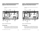
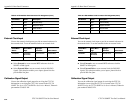
Programmer Manual. Figure G–3 shows how the pins are numbered
on the RS-232 port. Table G–2 lists the pin assignment for the
RS-232 port on the CTS 710 rear panel.
15
96
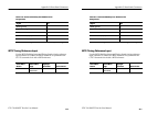
Figure G–3: The RS-232 Port
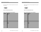
Table G–2: RS-232 Rear Panel Connector Pin Assignment
Pin Number Name Description
1 DCD Data Carrier Detect
2 RxD Receive Data
3 TxD Transmit Data
4 DTR Data Terminal Ready
5 GND Signal Ground
Appendix G: Rear-Panel Connectors
CTS 710 SONET Test Set User Manual
G–3
GPIB Port
The GPIB (General Purpose Interface Bus) port is used for remote
control of the CTS 710. For detailed information on remote control
of the CTS 710, see the CTS 710 SONET Test Set Programmer
Manual (Tektronix part number 070-8924-XX)
RS-232 Port
The rear panel RS-232 connector is used to connect to printers and
instrument controllers. Set the RS-232 parameters for printers on the
PRINTER SETUP page of the UTILITY menu. Set the RS-232
parameters for instrument controllers on the REMOTE CONTROL
page of the UTILITY menu. You can find more detailed information
on remote control of the CTS 710 in the CTS 710 SONET Test Set
Programmer Manual. Figure G–3 shows how the pins are numbered
on the RS-232 port. Table G–2 lists the pin assignment for the
RS-232 port on the CTS 710 rear panel.
15
96
Figure G–3: The RS-232 Port
Table G–2: RS-232 Rear Panel Connector Pin Assignment
Pin Number Name Description
1 DCD Data Carrier Detect
2 RxD Receive Data
3 TxD Transmit Data
4 DTR Data Terminal Ready
5 GND Signal Ground