


CTS 710 SONET Test Set User Manual
G–1
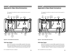
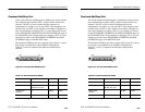
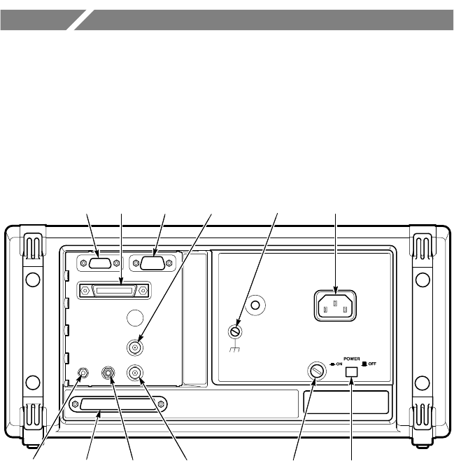
Appendix G: Rear-Panel Connectors
This appendix describes the connectors located on the rear panel of
the CTS 710.
Power
Connector
Principal
Power
Switch
Fuse
VGA
Video
Output
GPIB
Port
RS-232
Port
(Connector
Not Used)
1.544 Mb/s
BITS
Timing
Reference
Input
Overhead
Add/Drop
Port
Calibration
Signal
Output
Ground
External
Clock Input
(Optional)
Figure G–1: CTS 710 Rear Panel Connectors
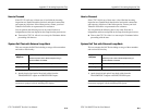
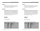
VGA Video Output
The CTS 710 can drive an external IBM-compatible VGA monitor.
There are no parameters to set in order to drive an external monitor.
The output is monochrome (green only); the resolution is 640 pixels
× 480 pixels. Figure G–2 shows how the pins are numbered on the
CTS 710 SONET Test Set User Manual
G–1
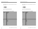
Appendix G: Rear-Panel Connectors
This appendix describes the connectors located on the rear panel of
the CTS 710.
Power
Connector
Principal
Power
Switch
Fuse
VGA
Video
Output
GPIB
Port
RS-232
Port
(Connector
Not Used)
1.544 Mb/s
BITS
Timing
Reference
Input
Overhead
Add/Drop
Port
Calibration
Signal
Output
Ground
External
Clock Input
(Optional)
Figure G–1: CTS 710 Rear Panel Connectors
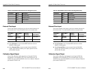
VGA Video Output
The CTS 710 can drive an external IBM-compatible VGA monitor.
There are no parameters to set in order to drive an external monitor.
The output is monochrome (green only); the resolution is 640 pixels
× 480 pixels. Figure G–2 shows how the pins are numbered on the