


Basic Test Procedures
CTS 710 SONET Test Set User Manual
3–9
connecting the upstream and downstream signals to the RECEIVE
input.
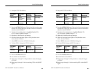
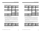
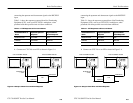
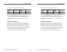
Table 3–1 shows the responses expected from Line Terminating
Equipment (LTE), such as an STS-3/STS-1 multiplexer, when
presented with three possible error and alarm conditions.
Table 3–1: LTE Responses to Errors and Alarms
Transmitted Error or
Alarm
Expected Upstream
Response
Expected Down-
stream Response
Section B1 Error Line FEBE none
LINE AIS LINE FERF PATH AIS
PATH FERF none PATH FERF
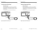
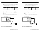
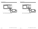
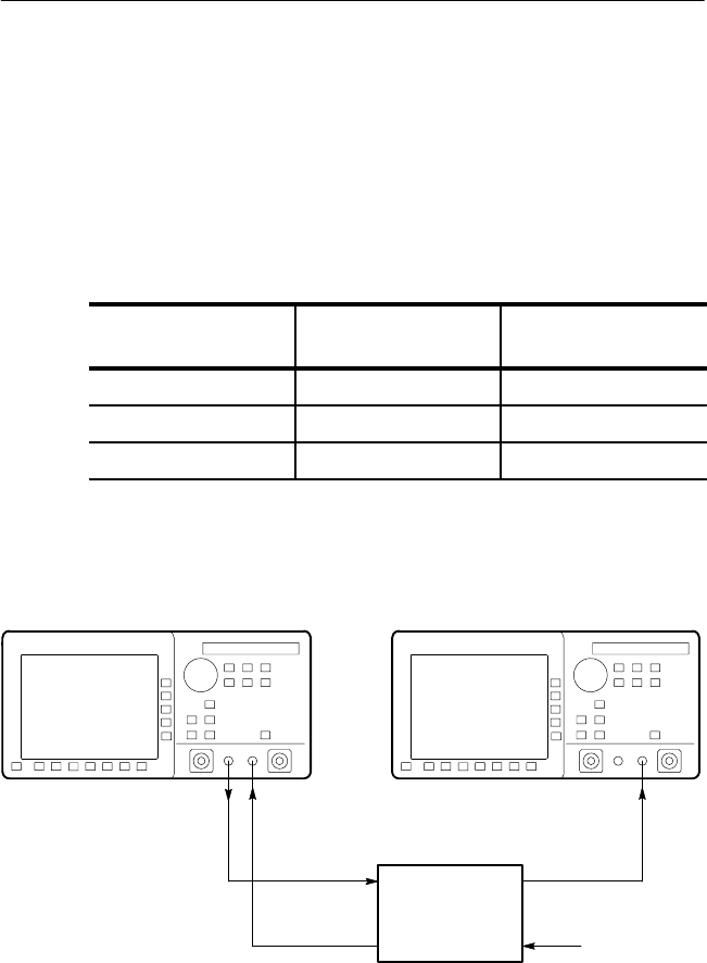
1. Connect two CTS 710s to an LTE as shown in Figure 3–4.
LTE
Downstream
Upstream
CTS 710 SONET Test Set CTS 710 SONET Test Set
All Signals are
STS-1
Figure 3–4: Setup to Check Error and Alarm Response
Basic Test Procedures
CTS 710 SONET Test Set User Manual
3–9
connecting the upstream and downstream signals to the RECEIVE
input.
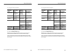
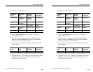
Table 3–1 shows the responses expected from Line Terminating
Equipment (LTE), such as an STS-3/STS-1 multiplexer, when
presented with three possible error and alarm conditions.
Table 3–1: LTE Responses to Errors and Alarms
Transmitted Error or
Alarm
Expected Upstream
Response
Expected Down-
stream Response
Section B1 Error Line FEBE none
LINE AIS LINE FERF PATH AIS
PATH FERF none PATH FERF
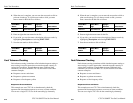
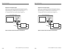
1. Connect two CTS 710s to an LTE as shown in Figure 3–4.
LTE
Downstream
Upstream
CTS 710 SONET Test Set CTS 710 SONET Test Set
All Signals are
STS-1
Figure 3–4: Setup to Check Error and Alarm Response