CTS 710 SONET Test Set User Manual
3–99
Setting SONET Receive Parameters
This section describes how to manually set the receive line rate,
define the STS under test, set the payload mapping and content,
check the received optical signal power, and view the overhead
bytes.
The CTS 710 SONET Test Set contains independent transmit and
receive modules. One set of parameters controls the transmit module
and a separate set controls the receive module. You can set the
receive parameters independent of the transmit parameters or you
can choose to link them to the transmit settings.
Pressing AUTOSCAN sets the receive parameters automatically
based on the received signal.
Steps for Setting Parameters
The sequence of steps for setting receive parameters varies with the
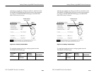
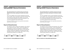
type of signal to be received. Figure 3–36 shows the sequence of
steps required to set the receive parameters for a SONET signal
without demapping a tributary signal. Figure 3–37 shows the steps
required to set the receive parameters for a SONET signal when
demapping a tributary signal. See page 3–89 for details on setting
tributary signal parameters (for example DS3).
Set
Rate
Set Signal
Structure
Specify STS
Under Test
Set
Mapping
Set Test
Pattern
Figure 3–36: Sequence for Setting SONET Signal Parameters


