


FR81 Family
20 FUJITSU MICROELECTRONICS LIMITED CM71-00105-1E
CHAPTER 3 PROGRAMMING MODEL
3.3
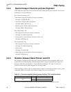
3.3.2 Program Counter (PC)
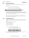
Program counter (PC) is a 32-bit register that indicates the address containing the instruction that is
currently executing.
Figure 3.3-2 shows the bit configuration of program counter (PC).
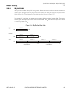
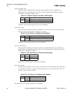
Figure 3.3-2 Program Counter (PC) Bit Configuration
The value of the lowest bit (LBS) of the program counter (PC) is always read as “0”. Even if "1" is written
to it as a result of address calculation of branching destination, the lowest bit of branching address will be
treated as "0". When the program counter (PC) changes after the execution of an instruction and it indicates
the next instruction, the lowest bit is always read as "0".
Following a reset, the contents of the Program Counter (PC) are set to the value (reset entry address)
written in the reset vector of the vector table. As the table base register (TBR) is initialized first by reset,
the address of the reset vector will be 000F FFFC
H
.
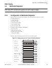
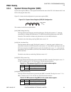
3.3.3 Program Status (PS)
Program status (PS) is a 32-bit register that indicates the status of program execution. It sets the interrupt
enable level, controls the program trace break function in the CPU, and indicates the status of instruction
execution.
Program status (PS) consists of the following 4 parts.
• System status register (SSR)
• Interrupt level mask register (ILM)
• System condition code register (SCR)
• Condition code register (CCR)
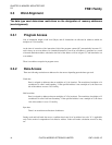
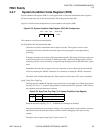
Figure 3.3-3 shows the bit configuration of program status (PS).
Figure 3.3-3 Program status (PS) Bit Configuration
The reserved bits of program status (PS) are all reserved for future expansion. The read value of reserved
bits is always "0". Write values should always be written as "0".
bit31
bit0
Initial value
XXXX XXXX
H
bit31 bit20bit27 bit15 bit10 bit7 bit0
ILMSSR SCR CCR
Reserved Reserved