FR81 Family
CM71-00105-1E FUJITSU MICROELECTRONICS LIMITED 29
CHAPTER 3 PROGRAMMING MODEL
3.3
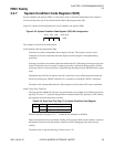
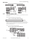
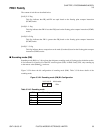
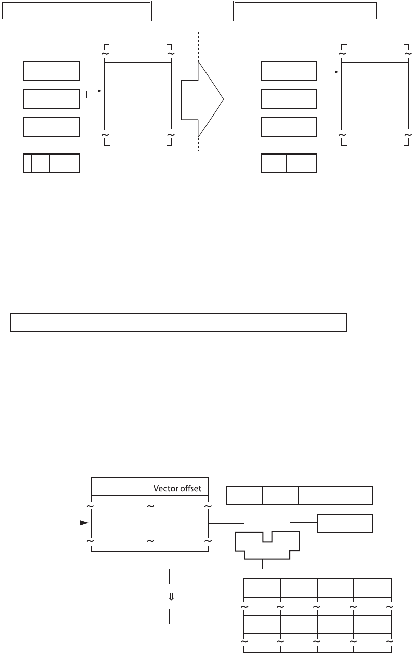
Figure 3.3-15 Example of User Stack Pointer (USP) Operation
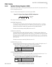
3.3.11 Table Base Register (TBR)
Table base register (TBR) is a 32-bit register that designates the vector table containing the entry addresses
for EIT operations.
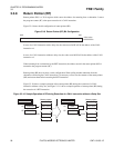
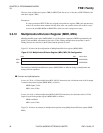
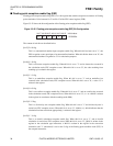
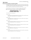
Figure 3.3-16 shows the bit configuration of table base register (TBR).
Figure 3.3-16 Table Base Register (TBR) Bit Configuration
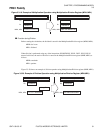
The address of the reference vector is determined by the sum of the contents of the table base register
(TBR) and the vector offset corresponding to the EIT operation generated. Vector table layout is realized in
word units. As the address of the calculated vector is in word units, the lower two bits of the resulting
address value are explicitly read as “0”.
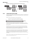
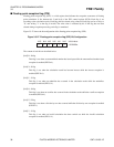
Figure 3.3-17 shows an example of table base register (TBR).
Figure 3.3-17 Example of Table Base Register (TBR) Example
Memory space
????????
????????
????????
Before execution of ST R13,@-R15
12345678
H
76543210H
SSP
USP
17263540
H
1
R13
CCR
FFFFFFFF
H
After execution of ST R13,@-R15
12345678
H
7654320CH
SSP
USP
17263540
H
17263540H
1
R13
CCR
SS
00000000
H
Memory space
FFFFFFFF
H
00000000H
bit31
bit0
Initial value
000F FC00
H
Vector correspondence table
Vector no.
Timer
interrupt
11
H 3B8H
bit31 bit0
Eaddr0 Eaddr1 Eaddr2 Eaddr3
Eaddr0 Eaddr1 Eaddr2 Eaddr3
PC
TBR
87654123H
Adder
Vector table
+0 +1 +2 +387654123
H+000003B8H
876544DBH
876544D8H


