


FR81 Family
CM71-00105-1E FUJITSU MICROELECTRONICS LIMITED 27
CHAPTER 3 PROGRAMMING MODEL
3.3
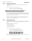
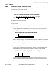
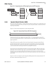
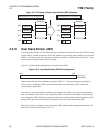
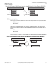
Figure 3.3-11 Sample Operation of RP during Execution of a RET Instruction.
3.3.9 System Stack Pointer (SSP)
The system stack pointer (SSP) is a 32-bit register that indicates the address to be saved/restored to the
system stack used at the time of EIT processing. The system stack pointer (SSP) is available when CPU is
in privilege mode (UM=0).
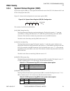
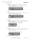
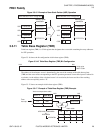
Figure 3.3-12 shows the bit configuration of system stack pointer (SSP).
Figure 3.3-12 System Stack Pointer (SSP) Bit Configuration
When the stack flag (S) in the condition code register (CCR) is "0", the general-purpose register R15 is
used as the system stack pointer (SSP). In a normal instruction, system stack pointer is used as the general-
purpose register R15.
When an EIT event occurs, regardless of the value of the stack flag (S), the program counter (PC) and
program status (PS) values are saved to the system stack area designated by system stack pointer (SSP).
The value of stack flag (S) is stored in the system stack as program status (PS), and is restored from the
system stack at the time of returning from the EIT event using RETI instruction.
System stack uses pre-decrement/post-decrement for storing and retrieving data. While saving data, after
performing a data size decrement on the value of system stack pointer (SSP), it is written onto the address
indicated by system stack pointer (SSP). While retrieving data, after the data is read from the address
indicated by the system stack pointer (SSP), a data size increment is performed on the value of system stack
pointer (SSP).
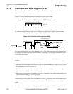
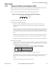
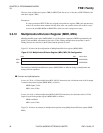
Figure 3.3-13 shows an example of system stack pointer (SSP) operation while executing instruction "ST
R13,@-R15" when the stack flag (S) is set to "0".
Memory space
CALL SUB1
After execution
1234567A
H
1234567A
H
PC
RP
Memory space
CALL SUB1
RET
RET
Before execution
SUB1
1234567A
H
PC
RP
SUB1 SUB1
ADD #1,R0 ADD #1,R0
bit31
bit0
Initial value
00000000
H