


CM71-00105-1E FUJITSU MICROELECTRONICS LIMITED 59
FR81 Family
CHAPTER 4 RESET AND "EIT" PROCESSING
4.6
A step trace trap is generated when the following conditions are met.
• Step trace trap flag (T) in the system condition code register (SCR) is set to "1".
• The currently executing instruction is not a delayed branching instruction
• User state in which CPU is in normal operation or debugging
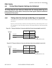
Step trace trap is not generated immediately after the execution of a delayed branching instruction. It is
generated after the execution of instruction within the delay slots.
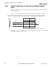
When the step trace trap flag (T) is enabled, non-maskable interrupts (NMI) and general interrupts are
disabled.
The following operations are carried out if a step trace trap is accepted during normal operation.
1. Transition to privilege mode is carried out, the stack flag (S) is cleared, the step trace trap flag (T) is
cleared, and 4 is set to the interrupt level mask register (ILM).
"0" → UM "0" → S "0" → T "4" → ILM
2. The contents of the program status (PS) are saved to the system stack
SSP - 4 → SSP PS → (SSP)
3. The contents of program counter (PC) of the next instruction is saved to the system stack
SSP - 4 → SSP next instruction address → (SSP)
4. The program counter (PC) value is updated by referring to the vector table.
(TBR + 3CC
H
) → PC
The address saved as program counter (PC) in the system stack represents the address of the next
instruction after the step trace trap.
The following operations are carried out for the brake process when a step trace trap is accepted in the user
state during debugging.
1. Transition to privilege mode is carried out, the stack flag (S) is cleared, the step trace trap flag (T) is
cleared, 4 is set to the interrupt level mask register (ILM), and then the mode is shifted to the debug
state.
"0" → UM "0" → S "0" → T "4" → ILM
2. The contents of the program status (PS) are saved to the PS save register (PSSR).
PS → PSSR
3. The contents of the program counter (PC) of the subsequent instruction are saved to the PS save register
(PCSR).
PC → PCSR
4. An instruction is fetched from the emulator debug instruction register (EIDR1), and the handler is
executed.
● Restrictions
The INTE instruction should not be used within the step trace trap handler. Use the OCD step trace
function for the device installed with OCD-DSU. Do not use the step trace trap explained in this section,
instead but always write "0" for step trace trap flag (T).