


FR81 Family
432 FUJITSU MICROELECTRONICS LIMITED CM71-00105-1E
APPENDIX
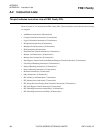
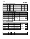
APPENDIX A Instruction Lists
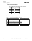
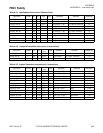
TYPE-B
2-digit hexadecimal value represents 4 bits of OP code as higher 1 digit and "0" for lower digit.
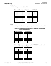
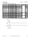
TYPE-E, TYPE-H, TYPE-I, TYPE-J, TYPE-K
3-digit hexadecimal value represents 12-bit OP code.
TYPE-F
2-digit hexadecimal value represents 8 bits with 3-bit 000
B
added below 5-bit OP code.
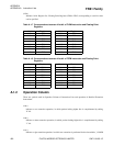
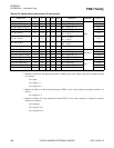
TYPE-L, TYPE-N
4-digit hexadecimal value represents 16 bits with 2-bit 00
B
added below 14-bit OP code.
TYPE-M
4-digit hexadecimal value represents 16-bit OP code.
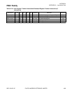
A.1.5 CYC Column
Symbols used in CYC Column of Instruction Lists and execution cycles of Detailed Execution Instructions.
Numerical values represent CPU clock cycles. Minimum of a to d is 1 cycle.
a
Memory access cycles. Cycles change depending on the access target. Minimum value is 1 cycle.
b
Memory access cycles. Cycles change depending on the access target. Minimum value is 1 cycle.
It is 1 cycle when uncompleted LD Instructions are less than 4 Instructions and Register which is the
object of load operation is not referred by the subsequent Instruction.
When uncompleted LD Instructions become more than 4 in number, an interlock will be applied from
that point till the completion of first LD Instruction and the number of execution cycles will be
increased by (Memory Access Cycles - Number of cycles from the issue of an Instruction till first LD
Instruction is completed).
When the Register which is target of load operation is referred to by the succeeding Instruction, an
interlock will be applied from that point and the number of execution cycles will increase by (Memory
Access Cycles - Number of cycle from the issue of an Instruction till an instruction refers to the targeted
Register + 1).