CM71-00105-1E FUJITSU MICROELECTRONICS LIMITED 433
FR81 Family
APPENDIX
APPENDIX A Instruction Lists
c
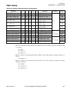
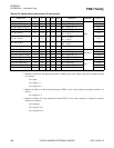
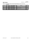
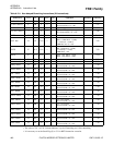
An interlock will be applied when the immediately next Instruction refers to Multiplication/Division
Register (MDH) and the number of execution cycles will be increased to 2. Otherwise it will be 1
cycle.
d
There will be 2 cycles when pre-fetching of Instruction in the Pre-fetch Buffer is not carried out.
Minimum value is 1 cycle.
A.1.6 FLAG Column
Symbols used for flag change in the Flag Column of Instruction Lists and Detailed Execution Instructions.
Represents change in Negative Flag (N), Zero Flag (Z), Overflow Flag (V), Carry Flag (C) of the Condition
Code Register (CCR).
C
Varies depending on the result of operation
-
No change
0
Value becomes "0"
1
Value becomes "1"
A.1.7 RMW Column
Symbols used in the RMW Column of Instruction Lists. It represents whether or not it is Read-Modify-
Write Instruction.
-
Instruction is not Read-Modify-Write Instruction.
❍
Instruction is Read-Modify-Write Instruction.
A.1.8 Reference Column
Represents the portion explained in “Chapter 7 Detailed Execution Instructions”


