


5700A/5720A Series II Calibrator
Service Manual
2-38
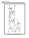
Output current on the +PA side is sensed between the emitter and base of Q203 by R202
and/or R201. Supply +PA shuts off to near 0V when enough current is flowing through
+PA to forward-bias Q203. Then, current though Q203 charges capacitor C209 through
R214 to a voltage above the threshold voltage at the inverting input of comparator
U201C. The overcurrent condition must persist for about 75 ms for C209 to charge
above the threshold. The output of U201 goes high, turning on Q207. This forces the
zener diode bias current to flow through Q207 instead of VR212 or VR216, leaving only
a few volts at the gate of Q202, thus shutting +PA off. The output of U201C also
saturates Q218 and reduces the comparator threshold voltage to near 0V. This provides
the comparator with hysteresis; C209 has to discharge close to 0V before +PA can turn
on again. The +PA supply cycles on and off as long as the overcurrent condition exists.
Transistor Q206 provides another current limit. While otherwise similar to the Q203
limit, the Q206 current limit turns on at 0.5A and turns off immediately without any
delay. The Q206 limit thereby protects the supply under short circuit conditions.
Current limiting on the -PA side works similarly to the +PA side with one difference.
That is that shutoff of -PA can happen under two circumstances:
• -PA is loaded beyond its current limit.
• +PA is shut off. (Shut off of -PA is slaved to shut off of +PA.)
2-70. Regulator/Guard Crossing Assembly (A17)
The Regulator/Guard Crossing assembly (A17) provides two separate functions: voltage
regulation for the analog power supplies, and digital control of the guard crossing. The
voltage regulation portion is described first followed by the digital control portion. Refer
to the schematic diagrams for the Regulator/Guard Crossing Assembly for this
discussion.
2-71. Voltage Regulator Circuitry
The regulator circuit receives unregulated dc from the regulator filter circuit on the
Filter/PA Supply assembly (A18) and provides 13 regulated dc outputs and 1
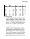
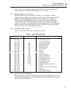
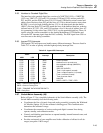
unregulated dc output for the various analog assemblies. Table 2-10 lists the regulated
supplies from the Regulator/Guard Crossing Assembly.
2-72. Regulated OSC Supplies
The +15 OSC and -15 OSC supplies are used exclusively by the Oscillator Output (A12)
and Oscillator Control (A13) assemblies. OSC COM is the return path for these supplies.
The +15 OSC uses the unregulated +15 OSCR from the Filter assembly and consists of
three-terminal TO-220 regulator U2 with heat sink, bypass capacitors C1 and C2, and
protection diodes CR2 and CR3. The -15 OSC uses the unregulated -15 OSCR from the
Filter assembly and consists of three-terminal TO-220 regulator U3 with heat sink,
bypass capacitors C4 and C5, and protection diodes CR5 and CR7. Capacitors C2 and
C5 improve the stability of U2 and U3 respectively. Diodes CR3 and CR5 protect U2
and U3 from reverse voltages. Diodes CR2 and CR7 protect U2 and U3 from input
shorts.