


Troubleshooting
Component-level Troubleshooting
5
5-43
logic high by measuring U15 pin 5. If the signal is incorrect, the control line WB
ON/OFF* from the Wideband Output (A5) assembly is probably at fault. If the
control line is correct check U15A and associated components.
Note
The input CLK and CLK* is a low-level (400 mV p-p) signal generated by
the Regulator/Guard Crossing assembly.
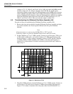
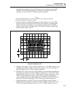
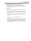
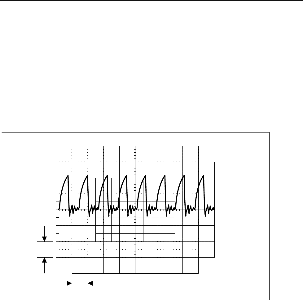
4. Check the 4 MHz to 8 MHz feedback signal. Set the Calibrator to 1V at 1.2 MHz,
operate. Connect an oscilloscope to TP15 and verify it displays a 4.8 MHz signal
similar to that shown in Figure 5-3. Use a frequency counter and verify that the
frequency of this signal is 4.8 MHz ±0.01%. If a failure is detected, continue with
step 5; otherwise skip to step 10.
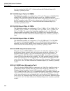
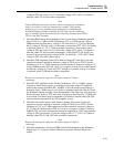
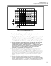
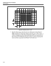
1 V
10 ms
F5-2.EPS
Figure 5-2. Waveform at TP1
5. Check the VCO Supply Voltage. Set the Calibrator to 1V at 1.2 MHz, operate. Using
a DMM measure the dc voltage at U3 pin 8 and verify it is -5V ±7%. If a failure is
detected, check Q2, Q3, U7, and associated components.
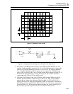
6. Check the VCO circuit. Power down the Calibrator, remove shorting header E6 from
the J6 pins, and connect an external variable dc reference(2V to 13V) to TP2. Power
up the Calibrator and set it for 1V at 1.2 Mhz, operate. Connect a frequency counter
to TP3. Vary the external dc reference from 2 to 12V and verify the frequency
counter reading changes from approximately 32 to 64 MHz. If a failure is detected,
check the VCO circuit containing U3, CR1, CR2, and associated components.
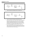
7. Check the dividers in U4 and U5. Power down the Calibrator, remove shorting
header E6 from the J6 pins, and connect an external variable dc reference (2 to 13V)
to TP2. Power up the Calibrator and set it for 1V at 1.2 MHz, operate. Connect a