Theory of Operation
Analog Section Detailed Circuit Description
2
2-129
990 Hz and five digits resolution from 1000.0 Hz to 1.1999 kHz. The resolution break
points are similar for the other ranges.
2-200. Reference Frequency Amp/Divider
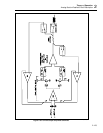
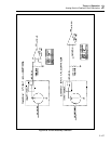
A 2-MHz reference frequency is generated by the reference frequency amp/divider
circuit as outlined on the schematic. This circuit uses the 8 MHz system clock lines CLK
and CLK*, generated by the Guard Crossing assembly (A17). This 8 MHz signal is a
low-level clock (200 mV p-p) and it is amplified to 5V p-p by comparator U13A. This
5V 8 MHz clock is turned off when the Hi-Res Oscillator is not being used by control
line HI-RES ON/OFF from the digital control circuit and nor gate U15D. The 8 MHz
clock is then divided to 2 MHz by flip-flops U14A and U14B to generate 2 MHz REF,
which is the reference frequency for synthesizer IC U16. It is filtered by R63 and C49 to
generate HI-RES CLOCK, which is monitored by the diagnostic circuit.
2-201. Phase-Locked Loop
The phase-locked loop circuit contains the phase detector/dividers, loop filter, and vco
(voltage-controlled oscillator) circuits as outlined on the schematic.
The phase det/dividers circuit contains synthesizer IC U16. This IC contains two
programmable divide-by-n counters and a phase detector. The divide-by-n counters are
controlled by inputs from the control bus, which are latched into internal latches on the
IC. Information on the control bus is entered and latched into U16 by NOR gate U15A
and control lines CS7* and WR*. The first divide-by-n counter is programmed to divide
2 MHz REF by 2000 to give 1 kHz, which is applied to one input of the internal phase
detector. The other divide-by-n counter is used to divide the feedback frequency at pin 3,
which is generated by the VCO circuit, by 6,010 to 12,000 in one-digit steps, and then
apply it to the second input of the phase detector. The loop is locked when the two inputs
to the phase detector are the same frequency and phase.
With the 1-kHz reference frequency and the feedback divider programmed between
6,010 and 12,000, the input frequency at pin 3 of U16 must be between 6.010 MHz and
12.000 MHz (1 kHz x 6010 = 6.010 MHz and 1 kHz x 12000 = 12.000 MHz).
Phase detector (U16) outputs ("0V" on pin 14 and "0R" on pin 15) are used by the loop
filter circuit, which controls the VCO circuit. If the divided feedback frequency is
greater than the 1 kHz reference frequency, or if the phase of the divided feedback
frequency is leading the output, 0V pulses low and output 0R remains high. If the
divided feedback frequency is less than the 1 kHz reference frequency, or if the phase of
the divided feedback frequency is lagging the output, then 0R pulses low and output 0V
remains high. When the feedback frequency and the 1 kHz frequency are the same and in
phase, the outputs 0V and 0R both remain high except for a short period when both pulse
low in phase. This condition occurs when the loop is locked.
Outputs from the phase detector (0V and 0R) are connected to the loop filter circuit
which contains the two op amps in U20. U20A and U20B amplify and filter,
respectively, any phase difference and apply it to varactor diode CR9 in the vco circuit.
The vco circuit contains varactor diode CR9 and vco IC U19. The vco frequency is
controlled by CR9, which gets its bias voltage from amplifier U20. This circuit is
designed to always operate over a 2:1 range from 6 MHz-12 MHz. To lock the loop,
amplifier U20 changes the bias on varactor diode CR9 until the divided vco frequency
has the same frequency and phase as the 1 kHz reference frequency at the input to the
phase detector in U16. Once the loop is locked, the output of the phase-locked loop
circuit is between 6 and 12 MHz. This output frequency is connected to the 5-500k
divider circuit for further division.


