


5700A/5720A Series II Calibrator
Service Manual
5-62
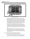
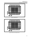
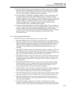
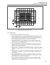
1 V
10 ms
F5-21.EPS
Figure 5-21. Waveform at TP5
9. Check the FILTER INPUT. Set the Calibrator to 6.5V dc, operate. Measure the
voltage with a DMM at TP1 (common to TP3 on the main board) on the DAC Filter
SIP assembly (A11A1). It should be a nominal +6.5V dc(±0.1V for an uncalibrated
instrument), free of distortion, and stable. If a failure is detected, check the DAC
Filter SIP assembly.
10. Check the DC AMP HYBRID. Set the Calibrator to 10V dc, operate. Measure the
voltage with a DMM at pin 18 (common to TP3) of the HR6 DC AMP HYBRID. It
should be a nominal +10V dc (±0.25V for an uncalibrated instrument), free of
distortion, and stable. If a failure is detected, check the HR6 Hybrid assembly and its
heater control circuit.
11. Check the OUTPUT BUFFER circuit. Set the Calibrator to 10V dc, operate. Measure
the voltage with a DMM at L10 (common to TP3). It should be a nominal +10V dc
(±0.25V for an uncalibrated instrument), free of distortion, and stable. If a failure is
detected, check U5 and its associated components.
12. Check the DAC OUTPUT SWITCHING. Set the Calibrator to 10V dc, operate.
Measure the DAC output voltage with a DMM a TP8 (common to TP12).It should
be a nominal +10V dc (±0.25V for an uncalibrated instrument). Set the Calibrator to
-10V dc, operate. Again check the voltage at TP8 (common to TP12). It should be a
nominal -10V dc(±0.25V for an uncalibrated instrument). If either of these voltages
are incorrect, check the output switching relays K1, K2, K8, and their drive circuitry.
13. Check the RANGE SELECT control line. Set the Calibrator to 10V dc, operate.
Using a DMM measure the RANGE SELECT control line at U37 pin 7 (common to
TP3). It should be -16 to -19V dc. Set the Calibrator to 20V operate and again
measure the RANGE SELECT control line for +4.0V to +11V. If either of these
measurements are incorrect, check U37, U8B, U8C, and their associated
components.