


Troubleshooting
Component-level Troubleshooting
5
5-61
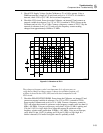
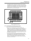
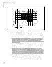
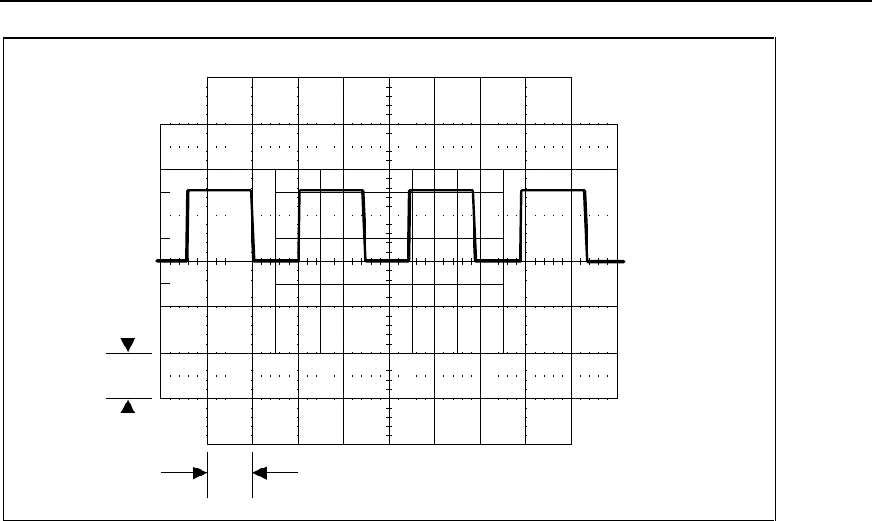
1 V
10 ms
F5-20.EPS
Figure 5-20. Waveform at TP7
Note
The duty cycle may differ from this figure. Using the Calibrator edit knob,
vary the second LSD of the Calibrator output display and verify that the
duty cycle of the signal at TP7 changes. If either of these displayed signals
are incorrect, skip to Duty Cycle Control Circuit.
6. Check the SERIES LINEARITY CONTROL CIRCUIT. Using a DMM measure the
voltage at U38 pin 6 (common to TP3). The voltage should be +23.0 to +26.4V. If
this voltage is incorrect, check U38 and Z2.
7. Check the NEG. OFFSET CIRCUIT. Using a DMM measure the voltage at U2 pin 1
(common to TP3). The voltage should be -13 to -14V which is the reference voltage
inverted. If this voltage is incorrect, check U2A and part of the HR6 resistor
network.
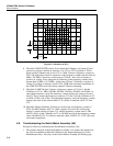
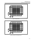
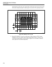
8. Connect an oscilloscope to TP5 (common to TP3), and set the Calibrator to 6.5V dc,
operate. Set the oscilloscope to 5V/div at 2 ms/div and verify the signal is similar to
that shown in Figure 5-21. If this signal is incorrect, check Q4, Q5, Q6, and Q7.