


Theory of Operation
Analog Section Detailed Circuit Description
2
2-67
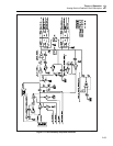
In the 22V range, Q20 is off and Q21 is on, which switches in the 40 kΩ feedback
resistors located on the HR6 assembly. Precise ratio matching of these resistors provides
high accuracy in the 22V range.
FET Q15 is on in the 22V range so that the output of the dc amplifier is half the output
of the DAC. This is necessary so that the output of the dc amplifier is approximately the
same as its inputs, which allows the bootstrap circuit to work.
The output buffer (U5) provides drive for the DAC output. It is used in a feedback loop
with the DC Amplifier Hybrid so that the dc accuracy is dependent upon the dc
amplifier, and the output drive capability is dependent on the output buffer.
The output buffer is current-limited to a short circuit current of about 60 mA. The short-
circuit protection circuitry works as follows:
1. The supply current is sensed by R23. When the output current of U5 reaches
approximately 50 mA, the voltage across R23 is large enough to turn on Q10.
2. As Q10 turns on, the voltage across R20 increases, and pulls down the supply
voltage at pin 4 of U5.
3. In order to prevent the supply of U5 from dropping below the input, Q8 saturates
turning on Q11 which shorts the input to FR1 COM.
4. When the short is removed, R22 and C41 cause Q11 to turn off slowly, which
prevents a large overshoot at the DAC output.
2-107. Sense Current Cancellation Circuit
This circuit uses op amp U1A and four resistors on the HR6 assembly. This circuit
supplies the sense current of equal, but opposite, polarity to the feedback resistors in the
22V range. This eliminates current in the sense lead during external sensing.
2-108. Linearity Control Circuit
The linearity control circuitry contains the series linearity control circuit and the shunt
linearity control circuit, as outlined on the schematic. These linearity control circuits
eliminate filter current in the series switch (Q5) and the shunt switch (Q6). This is
necessary because Q5 and Q6 have finite resistance (3 to 5Ω) and a small mismatch in
the resistances can cause a linearity error.
The series linearity control circuit uses op amp U38, resistor network Z2, and a single
19.996 kΩ resistor on the HR5 assembly. This circuit eliminates filter current in the
series switch Q5.
When the series switch (FET Q5) is on, it connects the 13V reference to the first channel
input of the filter, and FET Q4 is also turned on. This causes U38 to supply the current to
the filter through the 19.996 kΩ resistor in HR5 and Q4, which makes the resistance
from TP2 to TP5 look like near 0 ohms.
The shunt linearity control circuit uses op amp U2B, FET Q22, three 80 kΩ resistors on
the HR6 assembly, and one resistor in the HR5 assembly.
Op amp U2B is configured as an amplifier with an inverting gain of 1 in the 11V range,
and an inverting gain of 0.5 in the 22V range. This gain is determined by FET Q22 and
the three 80 kΩ resistors in the HR6 assembly.
When the shunt switch (FET Q6) is on, connecting the input of the filter to REFCOM,
the current from the filter flows through the two 40 kΩ resistor (pin 7 to pin 8) on the
HR6 assembly to the output of U2B. This cancels out the current that would flow
through Q6 which makes it look like 0Ω.