


5700A/5720A Series II Calibrator
Service Manual
5-50
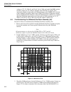
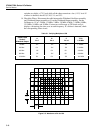
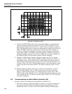
10 k
HR2
SHUNT
1.2
R14
2V ac
±10% K7C, K5D,
K10, K13
SCOM
Ω
Ω
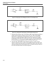
F5-9.EPS
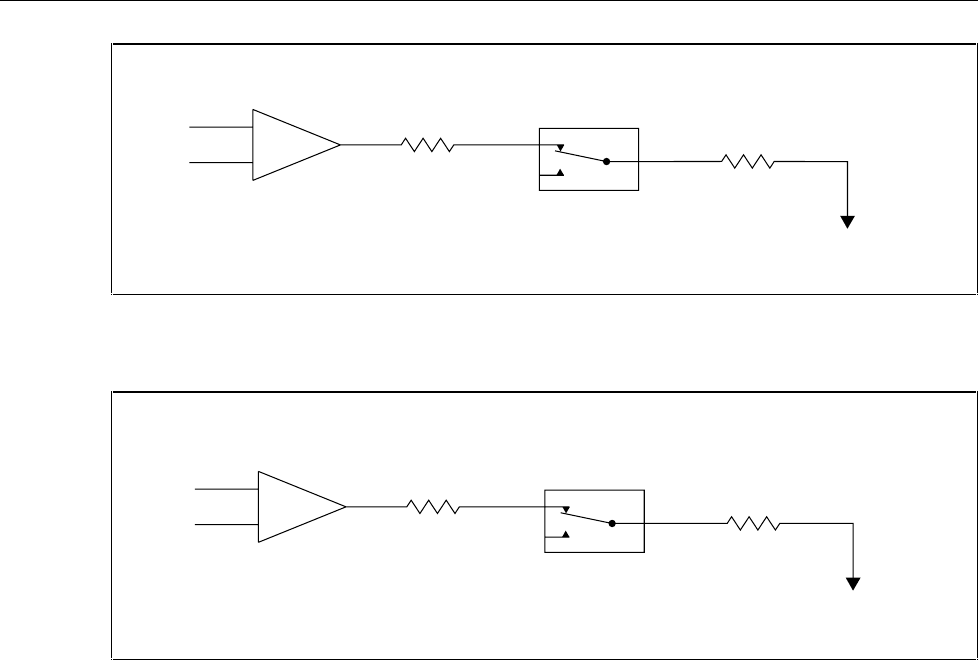
Figure 5-9. Verifying the 2.2 mA Range of the 220 µA /2.2 mA Amp Circuit
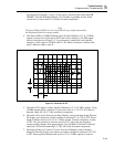
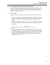
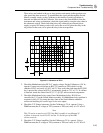
10 k
HR2
SHUNT
1.2
R14
2V ac
±10% K8C, K7A,
K5, K10, K13
SCOM
Ω
Ω
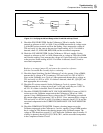
F5-10.EPS
Figure 5-10. Verifying the 22 mA Range of the 22 mA/220 mA Amp Circuit
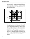
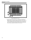
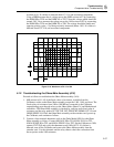
7. Check the 220 mA Range of the 22 mA/220 mA AMP. Set the Calibrator to 200 mA,
standby. Set the external ac reference to 4.6V (±0.1V) at 1 kHz. Using a DMM
measure the ac voltage at the collector of Q6 and verify it is 2.0V ac ±10%. If a
failure first verify the 10Ω shunt on HR2 is correct and it's connected to SCOM
through relays in K9C, K8C, K7A, K5D, K10, K13, and 1.2Ω load resistor R14 as
shown in Figure 5-11. If the shunt and output switching are correct, check Q6-Q13,
K4, and the associated components in the 22 mA/220 mA AMP circuit.
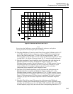
8. Check the NEG. FB BUFFER. Set the Calibrator to 200 mA, standby. Set the
external ac reference to 4.6V at 1 kHz. Using a DMM measure the ac voltage at the
collector of Q6 and Note the reading. Next, measure the voltage at TP3 and verify it
is the same as the previous Noted reading ±0.01%. If a failure is detected, check U2,
K5A, K6A, K8A,K9A and the associated components.