


5700A/5720A Series II Calibrator
Service Manual
2-72
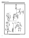
During the remainder store function, U29 amplifies and stores the difference between the
ADC INPUT and the adc dac output on one of the remainder storage capacitors, C89 or
C90. In this function, U29 is configured by the adc as a difference amplifier with a gain
of 16. The output of U29 is now the difference between the input voltage and the DAC
voltage, multiplied by 16. This voltage is stored on C89 or C90.
On the next cycle, this remainder voltage is switched into U29 as the input voltage
during the compare function.
Once this is repeated five times, U25 sends out an interrupt signal (ADC INT) to tell the
processor that it is waiting to read. To read the five passes of the adc, the processor reads
port A of the 82C55 five times.
For the most critical applications, the adc measures the output of the adc amplifier. Since
the output of the adc amplifier is adjusted until it reaches a checkpoint voltage, the adc
needs only to be repeatable at this voltage and low in noise. This reduces the constraints
on adc linearity and long term stability which allows a much simpler adc reference to be
used.
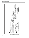
2-116. How the DAC is Used in Calibration
For internal and external calibration, the adc amplifier output is switched to ADC
INPUT.
The adc amplifier acts as a null meter. It measures the voltage difference between its
inverting and noninverting inputs and amplifies it by a gain of 11.
The adc amplifier can measure common-mode voltages up to 14V. Input switching
circuitry allows the DAC SENSE, buffered and unbuffered reference, RCL, and ADC
COM to be switched into the adc amplifier inputs.
To make a typical cal measurement, software sets the DAC to the approximate expected
common-mode voltage. The DAC is then switched into both adc amplifier inputs and an
adc reading is taken. This is the checkpoint measurement. It represents the adc amplifier
common-mode and offset error, and the errors in the adc and adc amplifier input
switching. The unknown voltage is switched into one input of the adc amplifier and the
DAC is adjusted by software until the adc reading matches the checkpoint reading. At
this point the unknown voltage is equal to the DAC voltage and is represented by the
current DAC counts.
2-117. DAC Assembly Calibration
The DAC assembly is completely characterized using a single external 10V source.
Calibration occurs in the following steps:
Ratio calibration of the first and second channels is performed first. The first channel
count is set for a DAC output of near 0V. The second channel count is set to its
minimum value of approximately 10,000. The DAC output is connected to the input of
the zero amplifier on the Switch Matrix assembly (A8) and its output connected to the
+input of the adc amplifier via the RCL line and the -input is connected to ADC COM.
The adc measures this value and stores it as a checkpoint reading. The first channel is
decremented by one count and the second channel is increased until the adc reads the
same as the previous checkpoint. The number of counts the second channel is increased
represents the channel ratio constant.
The ±11V and ±22V range zeros are calibrated next. This is done by the same technique
as the ratio cal except the checkpoint reading is obtained by connecting the input of the
zero amplifier on the Switch Matrix assembly to RCOM. The DAC output (DAC SENSE
CAL) is then connected to the zero amplifier input and adjusted until the adc reads the