


Theory of Operation
Introduction
2
2-5
2-1. Introduction
This section provides theory of operation in increasing level of detail. The calibrator is
first broadly defined in terms of digital functions (relating to the Digital Motherboard
assembly) and analog functions (relating to the Analog Motherboard assembly). The
interrelationship of these two areas is then explored in discussions of each output
function. Finally, the overall picture is rounded out with a discussion of system
interconnections.
Most of this section is devoted to detailed circuit descriptions, first of in the digital
(unguarded) section, then in the analog (guarded) section.
2-2. Calibrator Overview
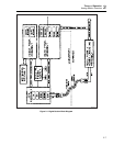
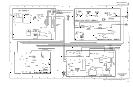
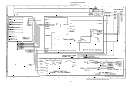
Figures 2-1, 2-2, and 2-3 comprise the block diagram of the Calibrator. These figures are
presented further on in the Analog Section Overview and the Digital Section Overview.
The Calibrator is configured internally as an automated calibration system with process
controls and consistent procedures. Internal microprocessors control all functions and
monitor performance, using a switching matrix to route signals between modules.
Complete automatic internal diagnostics, both analog and digital, confirm operational
integrity.
The heart of the measurement system is a 5 1/2-digit adc (analog-to-digital converter),
which is used in a differential mode with the Calibrator dac. (The dac is described next
under "Internal References.")
2-3. Internal References
The major references that form the basis of the Calibrator’s accuracy are the hybrid
reference amplifiers, patented Fluke solid-state thermal rms sensors, an extremely linear
dac, and two internal precision resistors.
2-4. Hybrid Reference Amplifiers
A precision source can only be as accurate as its internal references, so the dc voltage
reference for the Calibrator was chosen with extreme care. Years of data collection have
proven the ovenized reference amplifier to be the best reference device available for
modern, ultra-stable voltage standards.
In a microprocessor-controlled precision instrument such as the 5700A/5720A Series II,
the important characteristics of its dc voltage references are not the accuracy of the value
of the references, but rather their freedom from drift and hysteresis. (Hysteresis is the
condition of stabilizing at a different value after being turned off then on again.) The
5700A/5720A Series II hybrid reference amplifiers excel in both freedom from drift and
absence of hysteresis.
2-5. Fluke Thermal Sensor (FTS).
Thermal rms sensors, or ac converters, convert ac voltage to dc voltage with great
accuracy. These devices sense true rms voltage by measuring the heat generated by a
voltage through a known resistance.
Conventional thermal voltage converters suffer from two main sources of error. First,
they exhibit frequency response errors caused by component reactance. Second, they
have a poor signal-to-noise ratio because they operate at the millivolt level. The FTS has
a full-scale input and output of 2V and a flat frequency response.