


Theory of Operation
Analog Section Detailed Circuit Description
2
2-113
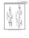
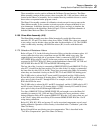
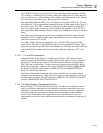
Lines PC0-PC3 of port C go to decoder U13 and to the Ohms Main assembly. Decoder
U13 enables two latch/driver ICs at a time. Setting the enable true (0V) causes the relay
coils to be driven on or off depending on the contents of the latch portion of the selected
ICs. Since these are latching relays, they are pulsed only briefly.
The outputs PB4, PB5 and PB6 of U11 are connected to the gates of FETs Q2, Q3 and
Q4 respectively. The Programmable Peripheral Interface IC turns them on for a one (5V)
and off for a zero (0V). PB7 is connected to the base of Q6 through R31. When PB7 is
true (5V), it turns on Q6, which turns on Q5, which in turn supplies +17S to U6. PC4
goes to the Ohms Main assembly where it strobes relay latch/drivers for the non-latching
relays.
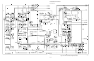
Line PC6 goes to the diagnostic circuit where it enables and disables output from the
multiplexer (U21). Connected to the input of the multiplexer are five voltage dividers
made from resistors in Z3 and Z4.
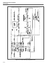
Two inputs to these dividers are connected. One is 10V OUT HI from the 2/5/10V
source circuit. The other is 2W COMP from the two-wire compensation circuit. These
inputs are connected to the SDL line by the multiplexer, where they are routed to the adc
circuit on the DAC assembly and measured during calibrator diagnostics. PC7 is not
used.
2-175. 1
,
1
.
9
,
and Short Resistance
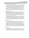
Although located on the Ohms Cal assembly, the 1Ω value, 1.9Ω value, and short
operate as part of the Ohms Main assembly, filling out the range of values available to
the operator. The 1Ω value is made of four 4Ω wirewound resistors in parallel (R41).
The 1.9Ω value is made of two 3.8 ohm wirewound resistors in parallel (R42). Relays
K4 and K5 connect the 1 ohm and 1.9Ω values to OHMS OUT HI and OHMS SENSE
HI. Relays K6 and K30 connect them to OHMS OUT LO and OHMS SENSE LO.
Relays K7 and K8 select the short.
The Ohms Cal assembly contains the relays that switch the low side of the selected
resistance onto the output bus. (High sides are connected to the output bus by relays on
the Ohms Main assembly.) Relay K24 connects OHMS OUT LO to OUT LO and K25
connects OHMS SENSE LO to INT SENSE LO.
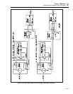
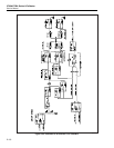
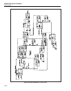
2-176. Two-Wire Ohmmeter Compensation Circuit.
Refer to Figure 2-32 for the following discussion. The Ohms Cal assembly contains a
two-wire lead drop compensation circuit that allows accurate calibration of two-wire
ohmmeters. The error normally encountered when calibrating a two-wire ohmmeter is
due to the voltage drop in the path resistance between the meter and the calibration
resistor. This circuit reduces the voltage drop to an insignificant level. Two wire
compensation can be used only with ohm meters that source continuous (not pulsed) dc
current.