


Troubleshooting
Component-level Troubleshooting
5
5-75
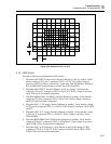
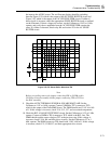
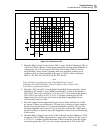
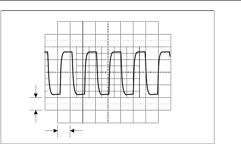
1 V
10 ms
F5-31.EPS
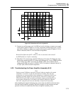
Figure 5-31. Waveform at TP3
3. Check the High Voltage Control in the 1100V ac range. Set the Calibrator to 220V at
110 Hz and 130 Hz, operate. At both output frequencies measure with a DMM the ac
voltage at pin 1A or 1C of connector P611 and verify it reads 220±0.2V. In this
range the High Voltage Control assembly and Power Amplifier assembly work
together to form an overall amplifier with a gain of -100. If a failure is detected,
check T1, K1, K14, K15, K16, K9, K6, K5, K12, and K3.
Note
Steps 4 through 7 check the operation of the High Voltage Control
assembly in the 1100V DC Range. If may be useful to refer to Figure 2-26
in the Theory of Operation Section.
4. Check the -SP C and +SP C from the High Voltage/High Current assembly. Set the
Calibrator to 0V standby. Using a DMM, measure the dc voltage at the cathode of
VR4 (-SP C) and verify it is between +13.2 and +14.2V. Next, measure the anode of
VR5 (+SP C) and verify it is-0.1V to -0.3V. If a failure is detected, the HV DC
Output Series Pass & Current Limit Circuit on the High Voltage/High Current
(A15)assembly may be at fault.
5. Check the output from the Magnitude Control circuit. Set the Calibrator to +220V
dc, operate. Connect an oscilloscope to TP3 and verify it displays a signal similar to
the previously shown Figure 5-31, except the amplitude is typically 10V p-p. The
measured amplitude may not be 10V p-p, for now just verify that the 1 kHz signal is
present. If a failure is detected, skip to the Magnitude Control circuit troubleshooting
in this section.
6. Check the High Voltage Control in the 1100V dc Range. Set the Calibrator to +220V
dc, operate. Using a DMM, measure the dc voltage across capacitor C1 and verify it
is 227V ±1V. A problem with the Magnitude Control circuit may cause this voltage
to be much greater than 227V. If no dc voltage is present check T1, K9, K6, CR1-