Theory of Operation
Digital Section Detailed Circuit Description
2
2-25
2-35. Interrupt Controller
PLD U10 is the priority interrupt controller. The interrupt controller reads incoming
interrupts and interrupt control lines, then encodes the highest priority interrupt into the
interrupt level for the 68HC000. When the 68HC000 responds to an interrupt request, it
asks the interrupt controller for an 8-bit vector that corresponds to the pending interrupt
of highest priority. The interrupt controller responds with the 4 LSB’s of the vector
according to how it is programmed. The 4 MSB’s are pulled up on resistor network Z1.
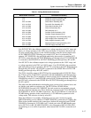
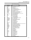
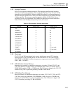
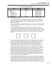
Table 2-5 shows the interrupts, their priority levels, and vectors.
Table 2-5. CPU Interrupts, Priorities, and Vectors
Interrupt Priority Level Vector (Hex)
NMI 7 - (not used)
DOGINTH 6 F4
BRPDRTINT* 5 F6
GCDUARTINT* 5 F7
EXDUARTINT* 5 F8
CLKCALINT* 4 F5
BRPIEEEINT* 4 F9
KEYBRDINT* 3 FA
BPSFAILINT* 2 FB
FANINT* 0 FF (not used)
RDY/BSYL 0 FF (not used)
No interrupt 0 FF
2-36. Glue Logic
ICs U2, U3, and U9 form the glue logic circuit, which keeps various CPU functions
running properly. The four OR gates in U9 and an inverter in U3 use control signals
UDS*, LDS*, and R/WR* from the microprocessor to generate control signals WRU*,
WRL*, RDL*, and RDU*.
2-37. RAM (Random-Access Memory)
Random-access memory is contained in three pairs of sockets, U19 and U20, U21 and
U22, and U40 and U41. These sockets accommodate either 32K x 8 or 128K x 8 static
CMOS RAM modules (32KB or 128 KB each). The Calibrator is shipped with U19-U22
installed, using 32K x 8 parts and providing 128 KB of static RAM.
2-38. ROM (Read-Only Memory)
Read-only memory is contained in three pairs of sockets, U15-U16, U17-U18, and U23-
U24. These sockets accommodate 27010 EPROMS, 128K x 8 devices (128 KB each).
Jumpers allow 256 KB devices to be used in their place. The Calibrator is shipped with
U15-U18 installed, providing 512 KB of EPROM.


