Troubleshooting
Interpreting Diagnostic Fault Codes
5
5-5
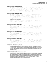
2713 A7: Hi-Res Loop In 100Hz Range
The instrument is set for 2.0V at 100 Hz operation. The input voltage to the VCO circuit
is resistively divided to create the control line HI-RES LOOP. HI-RES LOOP is
connected to the SDL line where it is measured by the adc circuit on the the DAC
assembly. A failure indicates the Current/Hi Res assembly (A7) is probably at fault.
2714 A7: Hi-res Loop In 1kHz Range
The instrument is set for 2.0V at 900 Hz operation. The input voltage to the VCO circuit
is resistively divided to create the control line HI-RES LOOP. HI-RES LOOP is
connected to the SDL line where it is measured by the adc circuit on the the DAC
assembly. A failure indicates the Current/Hi Res assembly (A7) is probably at fault.
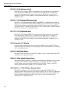
2715 A7: Hi-res Loop In 10kHz Range
The instrument is set for 2.0V at 11 kHz operation. The input voltage to the VCO circuit
is resistively divided to create the control line HI-RES LOOP. HI-RES LOOP is
connected to the SDL line where it is measured by the adc circuit on the the DAC
assembly. A failure indicates the Current/Hi Res assembly (A7) is probably at fault.
2716 A7: Hi-res Loop In 100kHz Range
The instrument is set for 2.0V at 70 kHz operation. The input voltage to the VCO circuit
is resistively divided to create the control line HI-RES LOOP. HI-RES LOOP is
connected to the SDL line where it is measured by the adc circuit on the the DAC
assembly. A failure indicates the Current/Hi Res assembly (A7) is probably at fault.
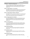
2717 A7: Hi-res Loop In 1MHz Range
The instrument is set for 2.0V at 121 kHz, 600 kHz, and 1.19 MHz operation. The input
voltage to the VCO circuit is resistively divided to create the control line HI-RES LOOP.
HI-RES LOOP is connected to the SDL line where it is measured by the adc circuit on
the the DAC assembly at each frequency. This fault occurs if the VCO input voltage is
not within 25% ±1.0V of the expected voltage. A failure indicates the Current/Hi Res
assembly (A7) is probably at fault.
2718 Fault In Setting Up AC For Diagnostics
This fault occurs if the diagnostics software was unable to properly set the Hi-Resolution
Oscillator hardware for diagnostics testing. A failure indicates the Current/Hi Res
assembly (A7) is probably at fault.
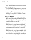
2719 A7: 8255 Was Reset
The control word of the 8255 on the Current/Hi Res assembly is determined to be
incorrect. A failure indicates the Current/Hi Res assembly is probably at fault.
2800 A11: 8255 Control Word
The diagnostics software reads the control word of the 8255 IC on the DAC assembly. A
failure indicates the DAC assembly (A11) is probably at fault.


