


5700A/5720A Series II Calibrator
Service Manual
2-18
2-20. Front/Rear Binding Posts
An internal cable can be configured to enable either the front panel or panel binding
posts. When compared to front panel binding posts, the rear panel provides the same
OUTPUT HI, OUTPUT LO, SENSE HI, SENSE LO, AND V GUARD functions. Also,
the rear panel provides an I GUARD (current guard) connection for use when the
Calibrator is supplying low-level ac current through a long cable. Use of the I GUARD
connection removes errors introduced by leakage through such cables. The rear panel
binding posts do not provide an AUX CURRENT OUTPUT connection. The procedure
to disable the front panel binding posts and enable the rear panel binding posts is to be
done at Service Centers, although it is described in this manual in Section 4.
2-21. Rear Panel Assembly (A21)
The Rear Panel assembly provides physical and electrical connections for the auxiliary
amplifiers, along with RS-232-C and IEEE-488 interface connections. Relays on the
Rear Panel assembly are used as the interfaces for the 5725A amplifier, or for switching
the PHASE LOCK IN and VARIABLE PHASE OUT signals.
A 5725A auxiliary amplifier can be physically connected to the Rear Panel assembly of
the 5700A/5720A Series II at J7. Only one amplifier can be in use at one time.
• The Rear Panel assembly provides relay switching for 5725A signals. Voltage
outputs from the 5725A are routed to the binding posts on the Calibrator. Current
outputs are soured at the 5725A OUTPUT binding posts. An alternate configuration
is also available, allowing for routing of Calibrator current outputs to the 5725A
OUTPUT binding posts.
2-22. Filter PA Supply Assembly (A18)
The Filter/PA Supply assembly incorporates two sections. The first section contains
filters and regulators for some of the in-guard low-voltage supplies, and the second
contains the power supply for the Power Amplifier output. Theory for each section is
discussed separately.
2-23. Digital Section Detailed Circuit Description
Detailed descriptions of each assembly in the digital section are provided here.
Simplified schematics and block diagrams are provided to supplement the text.
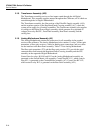
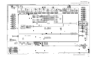
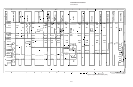
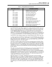
2-24. Digital Power Supply Assembly (A19)
The Digital Power Supply assembly receives ac voltages from the transformer and
provides five regulated dc voltages for use by the CPU, Front Panel assembly, Rear
Panel assembly, and the cooling fans. All power supply voltages are referenced to
COMMON, which is the transformer center tap for the ±12V supplies. Test points at the
top of the assembly can be used to check unregulated input voltages, and regulated dc
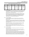
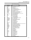
output voltages. Table 2-2 lists the supplies generated by the Digital Power Supply.