


5700A/5720A Series II Calibrator
Service Manual
2-104
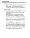
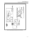
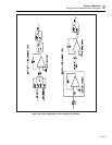
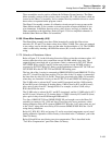
2-164. High Voltage Calibration
Refer to Figure 2-28 for the following discussion. The resistor network, (70 kΩ and 7
MΩ) which is part of the HR7 hybrid/resistor network assembly, determines the
accuracy of both 1100V ac and dc ranges. Calibration involves determining its offset and
gain constants.
To determine the offset, DAC outputs are connected to 70 kΩ input resistor by K1. The
output of the dc HV amplifier is inverted by U1 and its output is connected to the 7 MΩ
feedback resistor by K9, K8B, and K6. This configuration creates an inverting amplifier
with a gain of 100. Relay K9 connects the output of this amplifier to the RCL line, where
it is measured by the adc circuit on the DAC assembly (A11). The DAC’s adc circuit first
connects both its +input and -input to RCOM and takes a checkpoint reading. The +input
is then connected to the RCL line, which at this time is the amplifier output, and adjusts
the DAC output to obtain the same reading as the previous check point. This offset cal
constant is stored in nonvolatile memory.
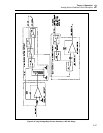
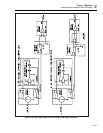
To determine the gain, the High Voltage/High Current assembly is configured in the ac
1100V range, except PA SNS DC is connected directly to the 7 MΩ input resistor of the
ac sense buffer by relays K8 and K6 instead of going through step-up transformer T1.
The 6.5V reference (BRF6) is connected to the Power Amplifier assembly (A16) which
is configured for an inverting gain of 20 to create a -130V output. The ac sense buffer
circuit attenuates this signal by 100 to generate 1.3V at its output. This 1.3V is connected
to the RCL line by relay K2 where it is connected to the +input of the adc circuit on the
DAC assembly. DAC OUT HI, which is connected to the -input, is adjusted until a null
is achieved. The gain can be determined by using this and the previous offset reading.
This determines the exact ratio of 70 kΩ and 7 MΩ resistor network on the HR7
assembly. This known ratio can then be used to output very accurate dc voltages in
1100V dc range.
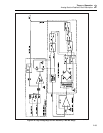
2-165. Calibration of the AC Function
The HR7 resistor network, previously calibrated at dc, is further characterized for its
frequency response. The Calibrator is placed in the ac 1100V range, except with HV
OUT and HV SENSE tied by relay K11 on the High Voltage/High Current assembly
(A15) instead of being tied at the load. The Oscillator Output assembly is set so the
output of the High Voltage/High Current Voltage assembly is approximately 695V at
130 Hz. This high voltage output (INT HV SNS) is connected to the AC CAL line,
through 399.6 kΩ resistor Z6, by relays K10 and K8A on the High Voltage assembly.
The AC CAL signal is routed to the Oscillator Control assembly (A12) where it is
measured by a 400Ω rms sensor.
Since the voltage is approximately 700V and it is applied through a 399.6 kΩ resistor
(Z6) to the 400Ω rms sensor, approximately 1.75 mA of current flows through the rms
sensor on the Oscillator Control assembly. A dc reading of the sensor, which is
approximately 0.7V (1.75 mA x 400Ω), is taken and then stored in memory with the
Oscillator Output level.
The Oscillator Output frequency is then increased to 500 Hz. The Oscillator Output level
is adjusted so the dc reading from the rms sensor is the same as for 130 Hz, and stored in
memory. This step is again repeated at 1 kHz. This characterizes the HR7 resistor
network’s frequency response. An accurate ac voltage can now be obtained at any
frequency between 50 Hz and 1 kHz. The theory of operation for the rms sensor is
contained in the Oscillator Control (A12) theory.