


5700A/5720A Series II Calibrator
Service Manual
2-6
After initial functional verification of the Fluke Thermal Sensors, their characteristics
only change by less than 1/10th of the allowed ac/dc error per year. External calibration
of the ac voltage function of the Calibrator consists of verifying that the Calibrator meets
its specifications.
2-6. Digital-to-Analog Converter (DAC).
A patented 26-bit dac is used in the calibrator as a programmable voltage divider. The
dac is a pulse-width modulated (pwm) type with linearity better than 1 ppm (part-per-
million) from 1/10th scale to full scale.
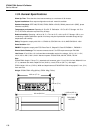
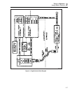
2-7. Digital Section Overview
The unguarded Digital Section contains the CPU assembly (A20), Digital Power Supply
assembly (A19), Front Panel assembly (A2), Keyboard assembly (A1), and the
unguarded portion of the Rear Panel assembly (A21). Figure 2-1 is a block diagram of
the digital section of the Calibrator.
Power for the digital assemblies and the cooling fans is supplied by the Digital Power
Supply assembly.
The CPU (central processing unit) assembly is a single-board computer based on the
68HC000 microprocessor. It controls local and remote interfaces, as well as serial
communications over a fiber-optic link to the crossing portion of the Regulator/Guard
Crossing assembly (A17). The guard crossing controls the guarded analog circuitry.
A Keyboard assembly provides the user with front-panel control of the Calibrator. It
contains four LED’s, a rotary edit knob, and a forty-five key keypad. It connects to the
Front Panel assembly via a cable.
The Front Panel assembly provides information to the user on an Output Display and a
Control Display. The Front Panel also contains circuitry that scans the keyboard and
encodes key data for the CPU.
The Rear Panel assembly includes digital interfaces for the following:
• IEEE-488 bus connection
• RS-232-C DTE serial port
• Auxiliary amplifier: the 5725A
2-8. Analog Section Overview
The guarded analog section contains the following assemblies:
• Wideband Output (A5) (Part of Option -03)
• Wideband Oscillator (A6) (Part of Option -03)
• Current/Hi-Res (A7)
• Switch Matrix (A8)
• Ohms Cal (A9)
• Ohms (A10)
• DAC (A11)
• Oscillator Control (A12)
• Oscillator Output (A13)
• High Voltage Control (A14)
• High Voltage/High Current (A15)
• Power Amplifier (A16)
• Regulator/Guard Crossing (A17)
• Filter/PA Supply (A18)