


5700A/5720A Series II Calibrator
Service Manual
5-78
operation refer to Figure 2-25 in the Theory of Operation section. During normal
operation in the 1100V ac mode, internal software monitors the output and makes
corrections or trips the instrument into standby. This internal monitoring can cause
difficulty when troubleshooting a faulty High Voltage assembly. If during the next
step 8 the instrument keeps tripping into standby, defeat the monitoring by
connecting a jumper from TP9 to TP10 on the DAC assembly.
8. Check the 1100V ac range. Set the Calibrator to 220V at 130 Hz, operate. Using a
DMM, measure the ac voltage at pin 1 of the HR7 resistor network. Note the DMM
reading and verify it is 220V ac ±0.1V. Next, measure the voltage at TP5 and verify
it is 1/100th of the voltage Noted at pin 1 of the HR7 resistor network. If a failure is
detected, check the HR7 Hybrid assembly, U2, U1, K6, K1, K4, and associated
components.
Note
Remove the jumper connecting TP9 to TP10 on the DAC assembly before
continuing. Steps 10 through 12 check the High Voltage/High Current
assembly in the 1100V dc range. To better understand the function of this
assembly during this mode of operation, refer to Figure 2-26 in the Theory
of Operation section.
9. Check the 1100VDC Range input voltage. Set the Calibrator to 220V dc, operate.
Using a DMM measure the dc voltage at TP1 and verify it is-2.2V ±1 mV. If a
failure is detected, check K1 and its drive circuit.
10. Check the 1100VDC Range DC HV Amplifier. Set the Calibrator to 220V dc,
operate. Measure the dc voltage at TP3 with a DMM and verify it is 0.55±0.2V.
Next, set the Calibrator to -220V dc, operate. Again measure the dc voltage at TP3
and verify it is now 2.3±0.2V. If a failure is detected, check the HR7 Hybrid
assembly, U2, K5, K7, K14, and associated components.
11. Check -SP C and +SP C in the 1100V dc range. Set the Calibrator to +220 Vdc,
operate. Using a DMM, measure the dc voltage at TP4 (-SP C) and verify it is
between +13.2 and +14.2V. Also measure the dc voltage at TP6 (+SP C) and verify
it is between -6 and -8V. Next, set the Calibrator to -220V dc, operate. Again
measure the dc voltage at TP4 and TP6. In this mode TP4 should be between +6 and
+8V, and TP6 should be between -13.2 and -14.2V. If a failure is detected, check
Q3, Q4, Q6, and associated components.
Note
Steps 12 through 14 check the High Voltage/High Current assembly in the
2.2A Current range. For these checks it will be necessary to install a
jumper connecting the front panel OUTPUT HI binding post to the
OUTPUT LO binding post. To better understand the function of this
assembly during this mode of operation refer to Figure 2-27 in the Theory
of Operation section.
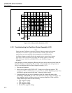
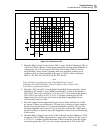
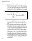
12. Remove the hybrid cover from the H4 assembly. Unsolder the right end of resistor
R37 (node with R37, Z5 pins 2 and 3), labeled G+ on the schematic, and lift this end
out of the circuit board. Connect an external ac reference to the lifted end of R37 and
reinstall the assembly on the extender card. Power up the Calibrator. Set the external
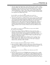
ac reference to 1V at 1 kHz and connect an oscilloscope to the output of the H4
Hybrid (node with R42, R44, and H4 pin 18). Verify the oscilloscope displays a
square wave similar to Figure 5-32. If a failure is detected, check the H4 Hybrid
assembly.