


Theory of Operation
System Interconnect Detailed Circuit Description
2
2-13
2-15. Ohms Functional Description
Two assemblies function as one to supply the fixed values of resistance:
• Ohms Main assembly (A10)
• Ohms Cal assembly (A9)
All of the resistance values except the 1Ω, 1.9Ω, and short are physically located on the
Ohms Main assembly. The 1Ω, 1.9Ω, and short are physically located on the Ohms Cal
assembly. The desired resistance is selected by relays on these Ohms assemblies and is
connected to the Calibrator binding posts by relays on the Analog Motherboard. The
Ohms Cal assembly also contains the appropriate circuitry to enable the Calibrator to
perform resistance calibration. Once calibrated, the Calibrator output display shows the
true value of the resistance selected, not the nominal (e.g., 10.00031 kΩ, not 10 kΩ).
Four ohms measurement modes are available. For the two-wire configuration,
measurement with or without lead-drop compensation sensed at the binding posts of the
UUT (using the SENSE binding posts and another set of leads), or at the ends of its test
leads is available for 19 kΩ and below. Four-wire configuration is available for all but
the 100 MΩ value.
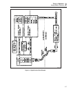
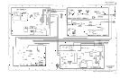
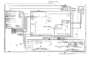
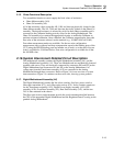
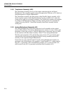
2-16. System Interconnect Detailed Circuit Description
The motherboard assembly contains the Digital Motherboard assembly (A4), and the
Analog Motherboard assembly (A3). These two Motherboards are mechanically fastened
together with screws. They are electrically connected by connectors P81 and P82 on the
Digital Motherboard and connectors J81 and J82 on the Analog Motherboard. AC
voltage taps from the Transformer assembly (A22) are connected to the Analog
Motherboard through these connectors. Refer to Figure 2-4 for an overview of system
interconnections. Figure 2-4 continues on the reverse side, showing system grounds.
2-17. Digital Motherboard Assembly (A4)
The Digital Motherboard contains the line-select switches, line fuse, power switch, a
fiber-optic transmitter (J73), and a fiber-optic receiver (J74). It also contains connectors
for the Transformer assembly (A22), Digital Power Supply assembly (A19), CPU
assembly (A20), Front Panel assembly (A2), Rear Panel assembly (A21), and the two
24V dc fans mounted in the chassis.
The fiber-optic receiver and transmitter provide the serial communication link between
the CPU on the unguarded Digital Motherboard and the Regulator/Guard Crossing on the
guarded Analog Motherboard.