Theory of Operation
Analog Section Detailed Circuit Description
2
2-59
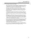
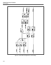
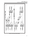
Calibration of the 10:1 divider ratio is accomplished by connecting the DAC assembly
output (DAC OUT HI and DAC SENSE HI) through relays K24 (A and B) and K6 to the
input of the 10:1 divider. DAC LO, PA COM, and R COM are connected to the common
of the 10:1 divider by relays K12, K11, and K21 respectively. The DAC output is set to
2.2V to produce approximately 0.22V at the output of the 10:1 divider (AC/DC mV).
Relays K17 and K29 direct this voltage to the internal cal zero amplifier, which is
configured for a gain of 10, giving 2.2V plus an unknown error at its output.
The equation for this output is the DAC output (2.2V) multiplied by the 10:1 divider
ratio (unknown) multiplied by the internal cal zero amp gain (calibrated, approximately
10). Once the output of the internal cal zero amplifier is determined, the 10:1 divider
ratio is the only unknown, so it can be calculated.
To determine the output of the internal cal zero amplifier for this configuration, a
checkpoint reading is first taken by connecting both inputs of the DAC’s adc amplifier to
the DAC output, which is set to 2.2V. This reading represents a null at 2.2V. The output
of the internal cal zero amplifier is then channeled to the RCL line by relays K31 and
K32 and to the +input of the adc amplifier on the DAC assembly with the DAC output
still connected to the -input. An adc reading is now taken and the checkpoint reading is
subtracted from it. This value is the adc’s representation of the deviation of the internal
cal zero amplifier output from 2.2V.
However, due to inaccuracy in the adc, an additional step must be taken. The -input of
the adc amplifier is connected to RCOM and the +input to the DAC output. The DAC
output is adjusted until the adc reads the previous value within the given tolerance. At
this point, the DAC output voltage represents accurately the deviation of the internal cal
zero amplifier output from 2.2V. The output of the internal cal zero amplifier is now
calculated, allowing the 10:1 divider ratio to be determined.
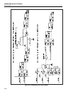
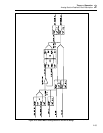
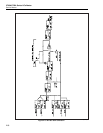
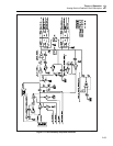
Refer to Figure 2-16 for the following discussion. Calibration of the 100:1 divider ratio
is similar to calibration of the 10:1 divider ratio. The 13V buffered reference (BRF13
and BSRF13) is connected to the input of the 100:1 divider pin 7 by relay K4 (A and B).
DAC LO, PA COM , and R COM are connected to pin 6 of the 100:1 divider by relays
K12, K11, and K21 respectively. The voltage at the divider output (pin 5) is
approximately 0.13V. Relay K7 connects the output of the 100:1 divider to the input of
the 10:1 divider. Relays K6 and K8 connect it to the ac mV CAL line, which is the input
to the internal cal zero amplifier. The result is 1.3V at the amplifier output. This voltage
is switched onto the RCL line by relays K31 and K32 to the DAC assembly, where the
DAC is nulled to it. At this point, the DAC voltage represents the internal cal zero
amplifier output and the 100:1 divider ratio is calculated.
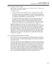
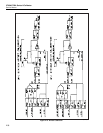
2-98. Internal CAL Zero Amplifier
The main function of the internal cal zero amplifier is to remove the offsets of each of
the dc ranges except the 1100V range. (The 1100V dc range is zeroed at the High
Voltage/High Current assembly.) The internal cal zero amplifier is switched into two
gain configurations for range zeroing; a gain of 130 for the 22V ranges and below, and a
gain of 10 for the 220V range. Each range is channeled into the internal cal zero
amplifier via relay K29. The range is then compared against 0V by connecting R COM
to the amplifier via FET Q7. For the 220 mV range, the reading for 0V (or checkpoint
reading) is taken by turning on Q11 instead of Q7 in order to achieve a 50Ω impedance.
The output of the amplifier is connected to the RCL line by relays K31 and K32, and
then channeled to the DAC assembly where the signal is measured by the adc.


