


5700A/5720A Series II Calibrator
Service Manual
5-56
Note
This 2V can be as much as ±0.12V if the DAC assembly is uncalibrated. If
a failure is detected, check the HR1 hybrid, U19, Q4, and associated
components.
6. Check the mV Dividers. Set the Calibrator to 200 mV at 1 kHz, operate. Using a
DMM measure the ac voltage at the cathode of CR6 (common to OUTPUT LO
binding post) and verify it is 200 mV ±1%. Next, set the Calibrator to 20 mV at 1
kHz operate and again measure the ac voltage at the cathode of CR6. Verify it is 20
mV ±1%. If a failure is detected, check the resistive dividers in the HR1 resistor
network and the associated relays.
5-10. Troubleshooting the Ohms Cal Assembly (A9)
Proceed as follows to troubleshoot the Ohms Cal assembly (A9):
1. The Ohms Cal assembly contains the two-wire lead drop compensation circuit,
calibration circuitry, the 1Ω, 1.9Ω, and short resistance values. All relays on the
Ohms Cal assembly are latching type. These relays are put in the set or reset position
and they remain in that position even after power has been removed. To troubleshoot
the path through the relays simply set the Calibrator to the function in which
problem is detected and then turn off the Calibrator. The relays remain in either the
set or reset position. Check individual relays by connecting an external power supply
(a typical 9V battery works well) across the set coil to place the relay in the set
position or the reset coil to place the relay in the reset position. Remove the rear
shield from the assembly and put it up on the extender card. Power up the Calibrator
and continue as follows.
2. Check the 1Ω, 1.9Ω, and short. Connect a four-terminal ohmmeter(such as a Fluke
Model 8505A) to the Ohms Cal assembly as follows. Connect 8505A IN HI to TP1,
8505A IN LO to TP 2, 8505A SENSE HI to TP5, 8505A SENSE LO to TP6. Set the
Calibrator to 1Ω, operate, EXT SNS, and verify the ohmmeter reads 1Ω ±0.1%. If a
failure is detected, check relays K4, K5, K6, and the four wire-wound resistors in
R41. Set the Calibrator to 1.9Ω, operate, EXT SNS, and verify the ohmmeter reads
1.9Ω ±0.1%. If a failure is detected, check relays K4, K5, K30, and the two wire-
wound resistors in R42. Set the Calibrator to 0Ω and verify the ohmmeter reads 0Ω
±0.1%. If a failure is detected, check relays K7 and K8.
5-11. Two-wire Compensation Circuit
Proceed as follows to troubleshoot the two-wire compensation circuit:
1. Check the +8A and -8A power supply for the two-wire comp. circuit. Set the
Calibrator to 100Ω, operate, and turn the two-wire comp on. Using a DMM measure
the dc voltage at TP8 (common to TP7) and verify it is +8.2V ±5%. Next, measure
the dc voltage at TP9 (common to TP7) and verify it is -8.2V ±5%. If these supply
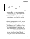
voltages are correct skip to step 2. If a failure is detected, first connect an
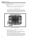
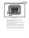
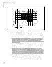
oscilloscope to pin 16 of U6 with the scope common connected to pin 13 of U6. Set
the oscilloscope to 5V/div at 10 us/div and verify it displays a waveform similar the
Figure 5-16. If a failure is detected, check U6, Q5, Q6, Control line PB7, and
associated components. If this signal is correct then check T1, CR1, CR2, CR9,
CR10, VR1, VR2, and associated components.
2. Set the Calibrator to 100Ω, operate, INT SNS, and 2-Wire Comp ON. Connect a
Fluke 8505A DMM, set to the 100Ω range, across the Calibrator OUTPUT HI and
OUTPUT LO binding posts. The current from the DMM should be 10 mA. Using
another DMM measure the dc voltage between pins 4 and 5 of U7 and verify it is