


5700A/5720A Series II Calibrator
Service Manual
2-94
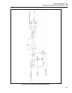
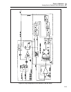
Power Amplifier dc gain of approximately -20 is calibrated next. The Power Amplifier is
configured as in the 220V dc operation, except the input is connected to the DAC’s 6.5V
reference BRF6 and BSRF6 by U2C and U2D respectively. The resulting -130V at the
Power Amplifier output is connected to the 175 kΩ end of the internal cal resistor
network by relay K3. The 25 kΩ end of this network is connected to DAC OUT HI and
DAC SENSE HI by relay K1. The output of the internal cal amplifier is connected to the
DAC’s adc circuit as in the previous steps, and the DAC OUTPUT is adjusted until
checkpoint is measured by the adc circuit. Since the exact attenuation of the resistor
networks is already known, the exact Power Amplifier output voltage can be calculated.
This in turn gives the exact Power Amplifier dc gain, since the exact value of 6.5V
reference BSRF6 is known.
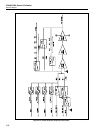
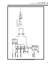
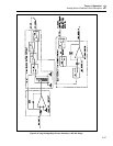
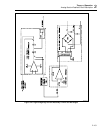
Attenuation of the 220V range ac attenuator (U4 and 396 kΩ/4 kΩ resistor network Z1)
is calibrated next. This is illustrated in Figure 2-24. First, the offset of the attenuator
circuit is measured by connecting the non-inverting input of U4 to ACOM through Q57
and thus to RCOM through Q51. Then, the Power Amplifier is configured for the 220V
dc range with its inputs connected to the DAC’s 6.5V reference BRF6 and BSRF6 by
U2B and U2C respectively. The resulting -130V is connected to the 400 kΩ input
resistor (Z1) of the 220V range ac attenuator by relay K16.
The +1.3V from the output of the attenuator circuit is connected to the RCL line by
relays K10B and K11. This voltage on the RCL line is connected to the +input of the adc
amplifier circuit on the DAC assembly. The DAC output is connected to the -input of the
adc amplifier circuit, and is adjusted until a null is achieved. The exact value of this
voltage is now known so the system software can compute the exact attenuator ratio.
The 220V range ac attenuator’s attenuation ratio can vary over the frequency range. This
variation can be accounted for if the frequency response of this network is characterized
at a few spot frequencies. This is done by connecting the Power Amplifier output, which
is set to 22V, to the AC CAL line by relay K14. The AC CAL line goes into the AC/AC
CAL thermal sensor located on the Oscillator Control assembly. The Power Amplifier
output of 22V is also attenuated through the AC Attenuator and sensed by the Oscillator
Control via OSC SENSE HI. The Oscillator adjusts its output, and hence the Power
Amplifier output, until the ac/ac cal thermal sensor measures the same ac level for all
these spot frequencies. The signal levels at OSC SENSE HI are stored in software at all
such points.
The ac/ac cal thermal sensor located on the Oscillator Control assembly has a flat
frequency response. The change in the ac attenuator’s output at various frequencies for a
constant thermal sensor output defines the frequency response of the Power Amplifier ac
attenuator. These computed ac attenuator factors are stored in the system memory and
are taken into account when the calibrator is configured to output ac voltages from the
Power Amplifier.
Output stage current is limited to about 250 mA; Q60 limits the current soured by the
output stage, and Q61 limits the current the output stage has to sink. Transistor Q62
limits the current flowing through the middle stage. These current limits both protect the
power amplifier circuitry and improve power amplifier transient response. Diode CR64
is a current source that maintains a current flow of at least 5 mA through the output
devices at all times.