


5700A/5720A Series II Calibrator
Service Manual
3-48
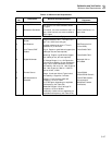
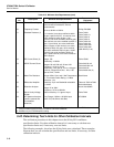
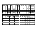
Table 3-15. Minimum Use Requirements (cont)
Item
No.
Description Minimum Use Specifications
Recommended
Equipment
9. Current Shunt Adapter
Used in conjunction with 5790A and A40-
series shunts to facilitate AC Current
measurements
Fluke 792A-7004
10. Frequency Counter
10 Hz to 30 MHz ±0.002%
Philips PM 6669
11. Standard Resistors (1)
0.1Ω nominal, true value certified to within
20 ppm, rated for 2A DC; 1Ω nominal, true
value certified to within 6 ppm; 1.9Ω
nominal, true value certified to within 6 ppm;
10Ω nominal, true value certified to within 6
ppm; 1 kΩ nominal, true value certified to
within 5.5 ppm; 10 kΩ nominal, true value
certified to within 3.5 ppm; 19 kΩ nominal,
true value certified to within 4 ppm; 10 MΩ
nominal, true value certified to within 15
ppm; 19 MΩ nominal, true value certified to
within 28 ppm
Fluke 742A-1
Fluke 742A-1.9
Fluke 742A-10
Fluke 742A-1k
Fluke 742A-10k
Fluke 742A-19k
Fluke 742A-10M
Fluke 742A-19M
L&N 4221B (0.1Ω)
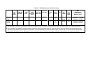
12. DC Current Shunt (2)
Range: 10A
Uncertainty: ±0.008%
Fluke Y5020
13. AC/DC Current Shunt
Ranges: 20 mA, 200 mA, 2A and 10A
Frequency: 10 Hz to 10 kHz
Uncertainty: ±310 ppm at 10 Hz; ±100 ppm
at 20 Hz; ±50 ppm at 40 Hz, 1 kHz; ±100
ppm at 5 kHz, 10 kHz
Fluke A40-20 mA
Fluke A40-200 mA
Fluke A40-2A
Fluke A40A-10A (2)
14. Metal Film Resistors
Values: 200Ω, 2 kΩ, and 1 MΩ Temperature
C°: T9 or better Power Rating: 1/4 Watt
Tolerance: ±1%
Stock Items
15. Differential Amplifier Sensitivity: 5 µV rms Bandwidth selectable
to 10 kHz
Tektronix 7A22 w/7000-
Series Mainframe
16. Distortion Analyzer
Range: 2V to 300V
Frequency: 10 Hz to 600 kHz
Krohn-Hite 6900B
17. Kelvin-Varley Voltage
Divider
Ratio uncertainty: ±0.1 ppm of input Fluke 720A
18. HF Spectrum Analyzer
(used in optional test
for wideband
distortion)
Freq. Range: 2 MHz to 120 MHz Input
Level: 3V (+20 dBm to -60 dBm)
HP 8590A
1: A DMM may be used for all but the 1
Ω
and 1.9
Ω
values. For those values using the DMM, a test method
using an external current source is used for low-value resistance.
2: Needed only for 5725A Amplifier testing.
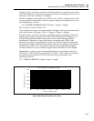
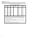
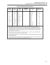
3-40. Determining Test Limits for Other Calibration Intervals
The verification procedures in this chapter test to the 90 day 99% confidence
specification limits. For other calibration intervals it is necessary to calculate new
specification limits and, if necessary, new test limits.
The following examples show how the 90 day limits were calculated. These examples
illustrate how you can calculate the specifications and test limits, if necessary, for other
calibration intervals.