


5700A/5720A Series II Calibrator
Service Manual
2-26
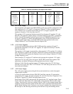
2-39. Electrically-Erasable Programmable Read-Only Memory (EEPROM)
IC U13 is an EEPROM. The socket accommodates a 32K x 8 device (32 KB of storage.)
A jumper is provided to allow an 8K x 8 (8 KB) device to be used in place of the 32 KB
device. The Calibrator is shipped with a 32KB EEPROM installed.
The EEPROM requires protection against inadvertent writes during power-up and
power-down sequences, which could corrupt calibration constants stored there by the
68HC000. The 32 KB EEPROM provides for software-controlled protection against
accidental writes.
Hardware is also used to further ensure data integrity. The EEPROMs are designed so
that writes to the device are prevented by holding the output enable line (NVMOE*) low.
Diodes CR5, CR6 and CR8, together with resistor R6, perform a wired-OR function for
three signals that control NVMOE*. Components R6, CR6 and C17 hold NVMOE* to a
valid logic low for typically 37.3 ms during power-up; 26.8 ms minimum, 49.6 ms
maximum. Diode CR7 provides a discharge path for C17 on power-down, allowing the
operator to quickly turn the Calibrator off then on again, without interfering with the
power-up charge time of the capacitor. Diode CR8 allows the normal microprocessor
read of the device to take place. And diode CR5 allows power monitoring IC U1 to hold
NVMOE* low when the +5V power supply drops below 4.5V on power-down or during
power glitches.
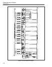
2-40. DUART (Dual Universal Asynchronous Receiver/transmitter) Circuit
The 68C681 DUART (U31) has several functions. Its primary function is to provide the
asynchronous serial lines that communicate with the Guarded Digital Controller over the
fiber-optic path off the Digital Motherboard. A 75451 driver chip (U32) drives the fiber-
optic transmitter on the digital Motherboard.
The DUART has 8 output lines that perform various functions. INTRCNTL1 and
INTRCNTL2 go to the interrupt controller and are fed back to the DUART inputs. These
are used by the interrupt controller to enable certain interrupts. Line SCLK is a test
output of the channel A serial clock.
The DUART monitors the EEPROM ready signal and the FANINT* signal. It also has a
spare serial channel that goes to connector J5. Components U44 and U43 convert the
TTL-level signals at the DUART to RS-232-C-level signals at J5.
The DUART generates its own DTACK signal, DRTDTK*, which is used by U5 to
generate system DTACK, DTACK*. A second DUART, U42, with associated RS-232-C
drivers and receivers is used only for test purposes. It generates its own DTACK, wire-
ORed to DRTDTK*.
2-41. Clock/Calendar Circuit.
Time and date information is stored in a battery-backed clock/calendar circuit consisting
of 32.768 kHz crystal Y3, 3V lithium battery BT1, clock/calendar IC U33, and
capacitors C10 and C11. The clock/calendar IC has the necessary circuitry internally to
switch operation from the power supply to battery BT1. Pull-up resistors in Z5 off U33
are to ensure low power operation when the +5V supply is off. U33 generates
CLKCALINT* under software control.