5700A/5720A Series II Calibrator
Service Manual
2-34
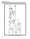
2-58. Unregulated OSC Supplies
Line OSC COM is the return path for the +15 OSCR and -15 OSCR supplies. These
supplies use a full-wave center-tapped configuration. They consist of bridge rectifier
CR3 and two filter capacitors, C4 and C6, for +15 OSCR and -15 OSCR, respectively.
Inputs are fused with 1.6A slow-blow fuses F1 and F2.
2-59. Unregulated LH Supplies
Line 5 LH COM is the return path for the +5 LHR and -5 LHR supplies. These supplies
use a full-wave center-tapped configuration, and consist of four diodes (CR1, CR2, CR4,
CR5) configured as a bridge rectifier.
Capacitors C2 and C3 filter +5 LHR, and C5 filters -5 LHR. Capacitor C1 reduces the
level of generated transients.
2-60. Unregulated S Supplies
The ±44 SR supplies use full-wave center-tapped rectifiers. Bridge rectifier CR6 is
followed by two filter capacitors C7 and C8 for the +44 SR and -44 SR supplies,
respectively. Inputs are fused by 0.5A slow blow fuses, F3 and F5. The ±17 SR supplies
also are full-wave center-tapped, consisting of four diodes (CR8, CR10, CR12, CR13)
configured as a bridge rectifier. Capacitors C13 and C14 filter the +17 SR supply, while
C15 and C16 filter the -17 SR supply.
2-61. Triac Circuit
The triac circuit protects the Calibrator if it is inadvertently plugged into an excessively
high line voltage. For example, it protects the Calibrator if it is plugged into a 230V line
when the rear panel line voltage select switches are set for 115V operation.
This circuit contains triac CR19, zener diodes VR20, VR21, resistor R1, and capacitor
C23. The zener diodes set a trip voltage of 82V. If the ac voltage across the main
transformer secondary for the ±17V supply exceeds 82V, the triac fires, shorting out the
winding, which causes the main transformer primary fuse to blow.
2-62. FR1 Supplies
Line FR1 COM is the return path for the unregulated +5 FR1R raw supply and the
regulated +5 FR1, and -18 FR1 supplies. Each supply uses a full-wave bridge
configuration.
The unregulated +5 FR1R supply consists of bridge rectifier CR15 and filter capacitor
C19. The input is fused with 1.6A slow-blow fuse F8. The regulated +5 FR1 supply uses
the unregulated +5 FR1R supply and contains regulator U2, filter capacitor C20, and
protection diode CR16.
The -18 FR1 supply consists of bridge rectifier CR17 and filter capacitor C21. Its input
is fused with 0.5A slow-blow fuse F9. The regulated -18 FR1 supply uses the
unregulated -18 FR1 supply and contains regulator U3, filter capacitor C22, and
protection diode CR18.
2-63. Unregulated FR1 Supply
FR1R COM is the return path for the unregulated +30 FR1 supply. This supply uses full-
wave bridge rectifier CR14 and filter capacitor C18. Its input is fused with 0.5A slow-
blow fuse F7.


