


5700A/5720A Series II Calibrator
Service Manual
2-8
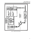
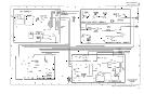
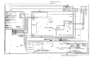
These analog assemblies are interfaced to the Analog Motherboard assembly (A3). The
guarded digital bus generated by the guard crossing portion of the Regulator/Guard
Crossing assembly controls all analog assemblies except the Filter/PA Supply. The
Guard Crossing interfaces with the unguarded CPU assembly via a fiber-optic link. The
Transformer assembly, along with the filter portion of the Filter/PA Supply assembly
and the regulator portion of the Regulator/Guard Crossing assembly, create the system
power supply for all the analog assemblies. The Power Amplifier Supply portion of the
Filter/PA Supply assembly provides the high voltage power supplies required by the
Power Amplifier assembly. The amplitudes of these high voltage supplies are controlled
by circuitry contained on the Power Amplifier assembly.
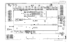
Figures 2-2 and 2-3 are block diagrams for the analog section of the Calibrator.
2-9. Functional Description Presented by Output Function
This part of the theory section presents Calibrator operation from the perspective of each
output function. It describes which assemblies come into play, and how they interact. It
does not provide a detailed circuit description. Refer to the individual assembly theories
further on in this section for detailed circuit descriptions.
2-10. DC Voltage Functional Description
The DAC assembly (A11) provides a stable dc voltage and is the basic building block of
the Calibrator. DC voltages are generated in six ranges:
• 220 mV
• 2.2V
• 11V
• 22V
• 220V
• 1100V
The 11V and 22V ranges are generated by the DAC assembly, with its output, DAC
OUT HI and DAC SENSE HI routed to the Switch Matrix assembly, where relays
connect it to INT OUT HI and INT SENSE HI. Lines INT OUT HI and INT SENSE HI
connect to the Calibrator binding posts by relays on the Analog Motherboard assembly
(A3).
The 2.2V range is created on the Switch Matrix assembly by resistively dividing by five
the 11V range from the DAC assembly. Relays on the Switch Matrix and Analog
Motherboard route the 2.2V range output to the Calibrator binding posts.
The 220 mV range is an extension of the 2.2V range. The Switch Matrix assembly
resistively divides by ten the 2.2V range to create the 220 mV range. Relays on the
Switch Matrix and Analog Motherboard route the 220 mV range output to the front
panel binding posts.
The 220V range is generated by the DAC and Power Amplifier assemblies. The Power
Amplifier amplifies the 11V range of the DAC assembly by a gain of -20 to create the
220V range. The output of the Power Amplifier is routed to the High Voltage Control
assembly (A14), where a relay connects it to PA OUT DC. Line PA OUT DC is routed
to the binding posts via relays on the Switch Matrix and Analog Motherboard.