


5700A/5720A Series II Calibrator
Service Manual
2-62
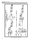
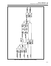
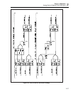
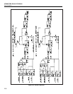
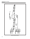
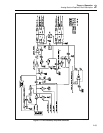
first input square wave is called the first channel. It is switched between the reference
voltage (13V) and 0V.
The filter’s second input square wave is called the second channel. It is switched between
approximately 0.78 mV and 0V. Its amplitude is derived by resistively dividing the 13V
reference. This second channel is used for extra resolution.
The filter rejects all ac components of the waveforms above 10 Hz. Since the frequency
of the square waves is 190 Hz, the output of the filter is a dc voltage which is the sum of
average voltages of the two waveforms. The Output Stage, which consists of the dc
amplifier hybrid and the output buffer, isolates the filter output from the DAC output and
gives current drive to the DAC output.
The output stage has a current limit of approximately 60 mA. It can be configured for a
gain of one for the 11V range, or a gain of two for the 22V range. Relays on the DAC
output lines allows them to be inverted for negative polarity.
To change the DAC voltage, the average value of the two square waves must be varied.
To determine the average value, multiply the waveforms amplitude by its duty cycle.
Vary the duty cycle and keep the amplitude fixed to change the DAC voltage.
For example, if the duty cycle of the first channel is 10% and the second channel 50%,
the overall average voltage would be:
(0.1 x 13V) + (0.5 x 0.78 mV) = 1.300390V.
The duty cycle resolution is 0.0024%, which gives a first channel resolution of 0.309 mV
and second channel resolution of 18.5 nV.
The duty cycle control circuitry creates the two digital square waves for the first and
second channels. These two waveforms are first run through optocouplers for isolation
and then into analog switching and level shifting circuits. These circuits derive the
proper signals to switch the input of the filter at the levels explained above.