5700A/5720A Series II Calibrator
Service Manual
2-32
interrupt by reading U24. On a read, indicated by a logic low on ENCODERCS*, U24
places the contents of a seven-bit up/down counter on the data bus. The counter keeps
track of the number of 180º rotations that have occurred between the time the interrupt
was first initiated and the counter is read. The counter is incremented or decremented
depending on the direction of rotation. Signal ENCODERRESET*, generated by U3 on a
write to the front panel encoder address space, clears the encoder interrupt.
2-54. Led Circuitry
The LED circuit controls the four light-emitting diodes mounted on the keyboard
assembly. It includes a 74LS373 8-bit latch (U10), and four resistors (R16-R19). The
respective LEDs light when the following states are active: external sense (EX SNS),
external guard (EX GRD), the wideband module is active (WBND), or when an attached
5725A Amplifier is active (BOOST).
Latch (U10) is controlled by the LED_LATCH_EN signal from the decoding PLD U3.
Signal LED_LATCH_EN latches the CPU data bus into the internal latches of U10 on a
write to the front panel LED memory space. This data appears at the output when control
line LEDENABLE* goes low. Control line LED_OUTPUT_CNTRL from U3 is inverted
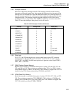
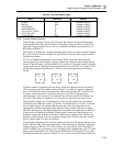
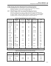
by U11C to create LEDENABLE*. Table 2-7 shows which line activates each LED.
Table 2-7. Control Lines for the Keyboard LEDs
Keyboard Led Control Lines
EX SNS LED1A
EX GRD LED2A
W BND LED2B
BOOST LED1B
2-55. Keyboard Assembly (A1)
The Keyboard assembly provides the operator with front panel control of the Calibrator.
It connects to the Front Panel assembly (A2) through a cable, and includes an
elastomeric keypad, four LEDs, and a rotary encoder (output adjustment) knob.
The elastomeric keypad and the printed circuit board form a 45-switch keyboard
arranged in eight columns and six rows. The keyboard scanner circuit on the Front Panel
assembly sequentially drives columns one through eight. When a key is pressed, a low
appears on the corresponding row as the key's column is scanned. The keyboard scanner
circuit encodes the key's row and column location, then takes appropriate action.
The four LEDs (CR1-CR4) are controlled by the LED driver circuit on the Front Panel
assembly. LED CR1 is turned on by LED1A when external sensing is selected. LED
CR2 is turned on by LED2A when external guard is selected. LED CR3 is turned on by
LED2B when the wideband module is active. LED CR4 is turned on by LED1B when an
attached 5725A Amplifier is active.
The rotary output adjustment knob activates UUT "Error Mode", allowing the operator
to adjust the Calibrator output. It can also control the phase shift for variable phase
output. The knob assembly consists of two optocouplers (DT1 and DT2) and a
magnetically-detented rotary knob. As the knob is turned, optocoupler DT1 generates a
pulse signal on ENCODERA and optocoupler DT2 generates a pulse signal on
ENCODERB. These signals are routed to the Front Panel assembly where knob encoder
circuitry interprets these signals and takes appropriate action. The current-limiting
resistor for LEDs within DT1 and DT2 is located on the Front Panel assembly.


