5700A/5720A Series II Calibrator
Service Manual
5-66
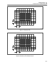
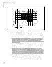
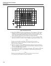
1 V
10 ms
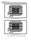
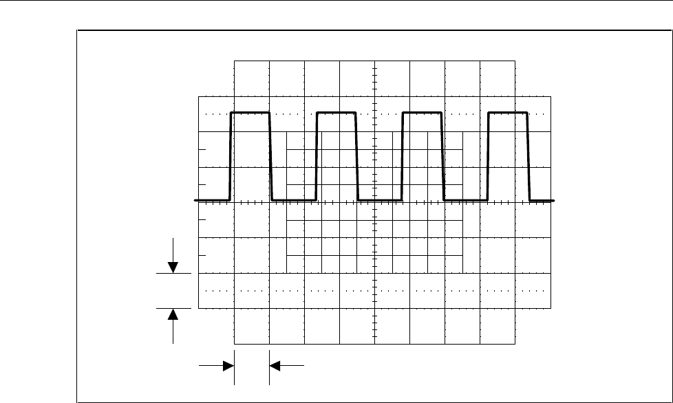
F5-25.EPS
Figure 5-25. Waveform at TP6
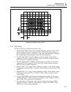
10. Check CH1 SERIES B. Connect an oscilloscope to TP4 (common to TP3).Set the
Calibrator to 6.5V dc, operate, and the oscilloscope to 10V/div at 2 ms/div. The
oscilloscope should display a signal similar to previously shown Figure 5-19. If a
failure is detected, check Q33, Q34, and their associated components.
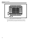
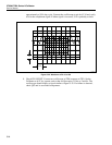
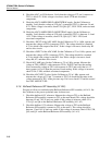
11. Check CH2 FLOATING. Connect an oscilloscope to U12 pin 7 (common to TP3)
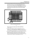
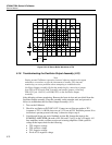
and set it to 10V/div at 2 ms/div. Verify it displays a signal similar to Figure 5-26.
Note
The duty cycle may differ from Figure 5-26. At this time just verify the
amplitude and a sharp rise and fall time. If a failure is detected, check U12
and its associated components.
12. Check 3V reference. Using a DMM measure the voltage at U11 pin 3(common to
TP3) for a nominal 3V dc. If this voltage is incorrect check U1B and the associated
resistors on the HR5 Hybrid assembly.
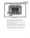
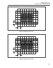
13. Check CH2 FILTER INPUT. Connect an oscilloscope to TP7 (common to TP3) and
set it to 2V/div at 2 ms/div. Verify it displays a signal similar to the previously
shown Figure 5-20.
Note
The duty cycle may differ from Figure 5-20. If a failure is detected, check
U11, Q30, Q31, Q32, and their associated components.


