


5700A/5720A Series II Calibrator
Service Manual
5-72
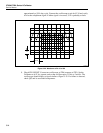
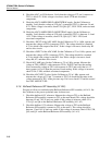
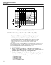
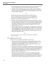
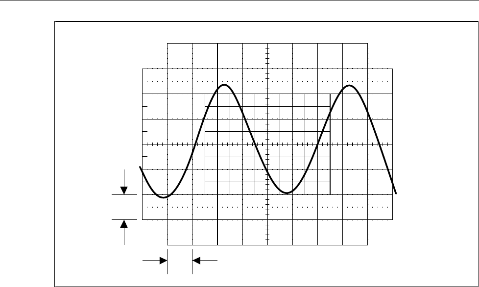
1 V
10 ms
F5-30.EPS
Figure 5-30. AC Sense Buffer Waveform at TP6
5-18. Troubleshooting the Oscillator Output Assembly (A13)
Note
During normal Calibrator operation, internal software monitors the output
and makes corrections or trips the instrument to standby. This internal
monitoring can cause problems when attempting to troubleshoot the
Oscillator Output assembly. Defeat the monitoring by connecting a jumper
from TP9 to TP10 on the DAC assembly and another jumper connecting
SDL (P511 pin 11A/11C) to SCOM (TP1) on the Oscillator Output
assembly.
After defeating software monitoring, Remove the front air duct and rear shield from the
Oscillator Output assembly. Place the assembly on the extender card, and proceed as
follows to troubleshoot the Oscillator Output Assembly (A13):
1. Turn on the Calibrator.
2. Check for oscillation at INT OSC OUT. Connect an oscilloscope probe to TP3
(common to TP1). A 100 Hz sine wave at 5.12V rms ±0.25V should be present. If no
oscillation is present proceed with step 3; otherwise skip to step 4.
3. Unsolder and lift up one end of feedback resistor R6. Jumper the input to the
SUMMING AMPLIFIER (the node of R1, R6, and U3 pin 5) to the +5S supply. All
four amplifiers in this oscillator section are inverting amplifiers. With a positive
voltage at the input, check for the following:
• TP5: negative voltage
• TP4: positive voltage
• TP3: negative voltage
• Pin 6 of U8: negative voltage