


5700A/5720A Series II Calibrator
Service Manual
2-96
2-155. High Voltage Assemblies (A14 and A15)
The High Voltage/High Current assembly (A15) and the High Voltage Control assembly
(A14) are used in with conjunction with other assemblies in the calibrator to generate the
±1100V dc, 1100V ac, and the 2.2A ranges. The two assemblies work together in
generating these ranges. This theory of operation explains how these ranges are
generated and discusses the individual circuits on each assembly. Refer to the High
Voltage/High Current assembly simplified schematics (Figures 2-24 through 2-28) or the
schematic diagram to understand this theory of operation better.
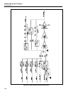
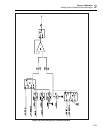
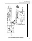
2-156. 1100V AC Range
Refer to Figure 2-25 for the following discussion. The ac signal generated by the
Oscillator Output assembly (A13) is amplified by the Power Amplifier assembly (A16).
The output of the Power Amplifier, PA OUT DC, is routed to the High Voltage Control
assembly (A14), where it is further amplified by transformer T1 to generate the 1100V
ac range. This high voltage signal from T1 is also the feedback signal to the Power
Amplifier assembly. Relays K14-K16 connect the transformer windings in series during
operation below 120 Hz.
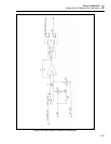
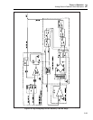
Line PA OUT DC is connected to one side of the primary winding of step-up
transformer T1 by relay K1 on the High Voltage Control assembly (A14). The other side
of the primary winding is tied to PA COM through R67. One side of the secondary
winding is tied to PA COM by relays K9 and K6. The other side of the secondary
winding, the high voltage ac signal, is connected to HV OUT by relays K5, K12 and K3.
Line HV OUT is connected to the OUTPUT HI binding post by relays K9 and K1 on the
motherboard.
This high voltage ac signal is also connected to HVAC by relay K5. Line HVAC is the
feedback signal to the Power Amplifier assembly. During high voltage operation, the
input resistance of the Power Amplifier assembly is 5 kΩ. Line HVAC is connected to
the feedback resistance, which is a series of resistors totaling 500 kΩ. This creates a gain
of 100 to the Oscillator Output.
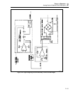
The SENSE HI binding post is connected to HV SENSE by relays K3, K2, and K10 on
the motherboard. HV SENSE, which is tied to HV OUT at the load, is connected to INT
HV SNS by relay K13 on the High Voltage Control assembly (A14). INT HV SNS is
routed to the High Voltage/High Current assembly (A15), where it is connected to the ac
sense buffer circuit by relay K6. This circuit attenuates the high voltage signal by 100
and connects it to OSC SENSE HI through relay K4B. The level of attenuation is
determined by the 7 MΩ input and 70 kΩ feedback resistors on the HR7 assembly. OSC
SENSE HI is used by the Oscillator Output assembly, which adjusts its output signal to
maintain an exact feedback signal level. HV OUT and HV SENSE are routed to the High
Voltage assembly (A15) where components CR9, CR10, and R33-R35 keep the voltage
difference between them at 0.7V should they become disconnected at the load. Relay
K11 connects HV OUT to HV SENSE during calibration in the ac function.