


5700A/5720A Series II Calibrator
Service Manual
2-14
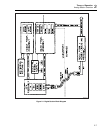
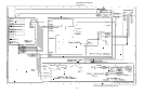
2-18. Transformer Assembly (A22)
The Transformer assembly receives ac line inputs routed through the A4 Digital
Motherboard. This assembly supplies outputs throughout the Calibrator, all of which are
routed through the A4 Digital Motherboard.
The Transformer assembly, the filter portion of the Filter/PA Supply assembly (A18),
and the regulator portion of the Regulator/Guard Crossing assembly (A17) create the
system power supply for all analog assemblies. The Transformer assembly also supplies
ac voltages to the Digital Power Supply assembly which generates five regulated dc
voltages for use by the CPU, Front Panel assembly, Rear Panel assembly, and the
cooling fans.
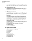
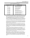
2-19. Analog Motherboard Assembly (A3)
The Analog Motherboard contains the connectors for all assemblies in the guarded
section of the calibrator. The Analog Motherboard also contains 13 relays, a fiber-optic
transmitter, a fiber-optic receiver, a cable for binding post connections, and two cables
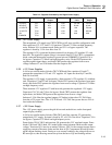
for the interface to the Rear Panel assembly. Table 2-1 lists Analog Motherboard
The fiber-optic transmitter (J72) and the fiber-optic receiver (J71) provide the serial
communication link between the Regulator/Guard Crossing assembly and the CPU
assembly on the unguarded Digital Motherboard.
Control lines for relays K1-K10 and K13 on the Analog Motherboard assembly are
generated on the Switch Matrix (A8) assembly. Control line RLY11*, which controls
relay K11, is generated on the Current/Hi-Res assembly (A7). Control line RLY12*,
which controls relay K12, is generated on the Rear Panel assembly (A21).