


Calibration and Verification
Full Verification
3
3-25
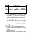
3-16. Resistance Verification Test
The following test requires testing at the high, low and intermediate values only. This is
because the 5700A/5720A Series II creates the other values of resistance from these
values. Use Tables 3-16 (5720A) and 3-17 (5700A) for test records. For the convenience
of anyone wishing to test the intermediate values, the tolerance limits are included.
Testing these values could be done using a Hamon-type ratio device and a very stable,
high-resolution bridge or DMM, or a combination of the two. Table 3-3 lists equipment
required for this test. See Table 3-15, Minimum Use Requirements, for substitution
information.
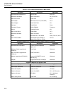
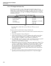
Table 3-3. Equipment Required for Resistance Testing
Equipment Decsription
Resistance
Standards
Fluke 742A Series in the following values: 1Ω, 1.9Ω, 10Ω, 10 kΩ, 19 kΩ, 10 MΩ,
and 19 MΩ
Current Source Fluke 5500A or 5520A
DMM Wavetek 1281 or HP 3458A
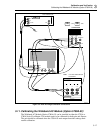
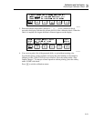
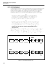
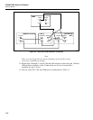
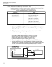
1. Connect the equipment as shown in Figure 3-8.
2. Set the Calibrator output to 1Ω with external sensing (EX SENS indicator lit) and set
the dc DMM to read dc V. Record the 1Ω resistance standard value on the test record
as the 1Ω STD RES VALUE.
3. Multiply the certified value of the 1Ω resistance standard by 0.1 and record the result
on the test record as the 1Ω STD VOLTAGE.
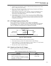
4. Connect the DMM across the sense terminals of the 1Ω resistance standard.
5. Set the direct current source for a nominal 100 mA output. Vary the source until the
DMM reading is as close as possible to the 1Ω Standard Voltage recorded in the
previous step. Record the DMM voltage reading on the test record as the
MEASURED 1Ω STD VOLTAGE.
Note
If the current source used has the resolution to achieve a voltage reading
to within ±5 ppm of the value in step 3, it is not necessary to calculate the
cal current in take next step. In this case, when you come to step 9 you
will simply multiply the voltage reading from step 9 by a factor of 10,
which is the same as dividing by 100 mA (0.1A).
6. Calculate the exact current by dividing the MEASURED 1Ω STD VOLTAGE by the
1Ω STD RES VALUE; record the result on the test record as the CAL CURRENT.
7. Enter the Calibrator displayed 1Ω value on the test record as the UUT 1Ω
DISPLAYED VALUE.
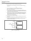
8. Transfer the dc DMM leads to the Calibrator sense terminals.
9. Enter the DMM voltage reading on the test record as the UUT 1Ω VOLTAGE.
10. Calculate the UUT true 1Ω resistance by dividing the UUT 1Ω VOLTAGE by the
CAL CURRENT.
11. Adjust the output adjustment knob for a UUT Control Display reading equal to the
true 1Ω resistance value calculated in the previous step. The error from the displayed
value is also shown on the Control Display. Enter the value of the error on the test
record as the UUT DEVIATION FROM DISPLAYED VALUE.