


Theory of Operation
Analog Section Detailed Circuit Description
2
2-35
2-64. FR2 Supplies
FR2 COM is the return path for unregulated +30 FR2R supply and regulated -5 FR2
supply. Each supply uses a full-wave, bridge configuration. The unregulated +30 FR2R
supply consists of bridge rectifier CR7 and filter capacitor C9. Its input is fused with
0.5A slow-blow fuse F4. The -5 FR2 supply consists of bridge rectifier CR11, filter
capacitor C11, regulator U1, bypass capacitor C12, and protection diode CR9. The input
is fused with 315 mA slow-blow fuse F6.
2-65. Filter/PA Supply (A18), Power Amplifier Output Supply Section
The power amplifier output power supply section of the Filter/PA Supply assembly
(A18) receives ac voltage from the main power transformer to generate power supplies
+PA and -PA for the output stage of the Power Amplifier assembly (A16). These two
power supplies can be switched between the following three modes of operation,
depending on the needs of the Power Amplifier.
• +PA and -PA to ±185V respectively.
• +PA and -PA to ±365V respectively.
• +PA and -PA are both turned off.
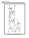
Figure 2-6 is a simplified schematic for the Power Amplifier Output Supply section of
this assembly.
2-66. ±PA Supplies Digital Control
Circuitry to control the three modes of operation of the +PA and -PA supplies is located
on the Power Amplifier Digital Control SIP assembly (A16A1). This SIP assembly is
mounted on the main Power Amplifier assembly (A16). Not on the assembly is the quad
comparator U201.
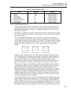
The main Power Amplifier assembly generates four control lines:
• +HI/LO V
• LO/HI I
• +ON/OFF
• H/LV S
Component Z201 pulls these signals up. At calibrator power up, the ±PA supply is off.
The Power Amplifier Digital Control SIP (A16A1) selectively pulls these control lines
low to achieve the two modes of operation. Pulling control lines +HI/LO V and
+ON/OFF low sets the +PA supply to +365V. Releasing +HI/LO V changes the +PA
supply to 185V.
The comparator (U201) provides level shifting to control the PMOSFETS in the -PA
circuit in a similar way. Signal -ON/OFF is generated from +ON/OFF, and -HI/LO V
from -H/LV. Control line +LO/HI I switches transistor Q217 which controls relay K201.
Relay K201 selects the current limit for both +PA and -PA supplies.