


5700A/5720A Series II Calibrator
Service Manual
2-100
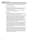
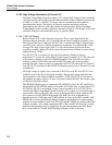
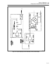
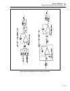
When the DAC assembly is set to the +11V range, the output from the High Voltage
assembly (with a gain of -100) is in the -1100V range. In this mode, -SP C is connected
to the collector of transistor Q3. The output from the dc HV amplifier follows a change
in the output voltage from the DAC assembly. This change controls how much Q3 is
turned on or off. As the DAC voltage is increased, Q3 turns on pulling -SP C to
PACOM. This causes the magnitude control circuit to increase the amplitude of HVCL
which increases the output from the Power Amplifier assembly, thus increasing the
HVDC until the overall loop is stable.
Operation in the +1100V range is basically the same, with transistor Q6 controlling +SP
C in the same manner as above.
Current limiting is provided by Q4 if more than 35 mA is drawn from the output. If this
condition occurs, Q4 pulls down CUR LIM, which is routed to the High Voltage Control
assembly. (CUR LIM is also called RST.) When CUR LIM (RST) is pulled low, PS OFF
goes high to turn off the square wave, HVCL, which shuts down the HVDC supplies.
The generation of HVCL is described under the heading, "Magnitude Control".
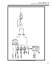
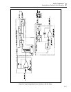
2-160. DC HV Amplifier
/
AC Sense Buffer
The dc HV amplifier and the ac sense buffer are basically the same circuit. The
configuration is changed to provide the 100:1 amplification of dc voltage and the 100:1
attenuation of the high voltage ac signal. This is defined by the way the HR7 resistor
network is configured in the circuit. This configuration is described in the 1100V ac
range and 1100V dc range theory.
This circuit contains the HR7 resistor network and the circuitry contained in detail 1 as
shown on sheet 1 of the High Voltage (A15) schematic. It is used in both the ac and dc
voltage modes. Detail 1 contains the HR7 hybrid assembly which is an op amp mounted
on a heated substrate hybrid bonded to a resistor network. The HR7 assembly gives this
circuit excellent dc characteristics of low offset, noise and drift. The hybrid heater
control circuit adjusts the base voltage of Q8 to deliver the proper power to the heater
resistor. This maintains the HR7 assembly at a constant temperature in spite of
environmental temperature variations. Transistor Q9 protects the hybrid in case Q8 fails.
The output of the HR7 op amp is connected to a faster op amp (U2), which provides
additional gain and a high slew rate. The output of U2 is called HVAMP OUT on the
schematic.
In the dc voltage function, the output of this circuit, configured as a dc HV amplifier, is
connected to the series pass circuit by relay K5B. Relays K5A, K7 and K14 add C4 in
parallel with the 7 MΩ feedback resistor in the HR7 assembly to filter the noise. ACOM
is connected to RCOM by relay K3.
During operation in the ac voltage function relays are positioned as shown on the
schematic. Components VR7 and VR8 provide input protection for the op amp on the
HR7 assembly. Op amp U1 is added to the circuit by relays K9, K8B and K6. This op
amp inverts HVAMP OUT so that the signal to OSC SENSE HI is in phase with the
output of the Oscillator assembly. ACOM is connected to OSC RCOM by relays K3 and
K4A.
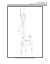
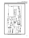
2-161. 2
.
2A Range
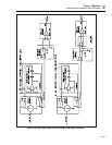
Refer to Figure 2-27 for the following discussion. Most of the same circuitry is used to
create the ac and dc 2.2A current ranges. The Current assembly (A7) is configured to the
22 mA range and connected to the IHV line which drives the 2.2A amplifier circuit on
the High Voltage assembly (A15). This 2.2A amplifier provides a gain of 100 to the 22
mA range from the Current assembly to create the 2.2A range.