


Troubleshooting
Component-level Troubleshooting
5
5-53
5. Check VCO Supply Voltage. Set the Calibrator to 2V at 1 kHz, operate. Using a
DMM measure the voltage at U19 pin 8 and verify it is -5.25V±7%. If a failure is
detected, check U18A, Q15, VR3, and associated components.
6. Check the VCO circuit. Power down the Calibrator, cut jumper E2 and connect an
external variable dc reference (2 to 12V) to TP11 (common to TP18). Power up the
Calibrator and set it for 2V at 1 kHz. Connect a frequency counter to TP13. Vary the
external dc reference from 2 to 12V and verify the frequency counter reading
changes from approximately 6 MHz to 12 MHz.
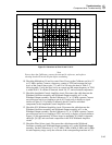
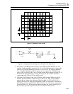
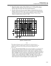
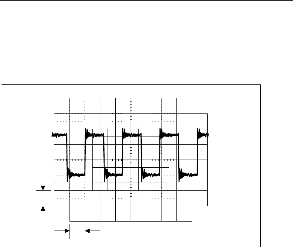
1 V
10 ms
F5-13.EPS
Figure 5-13. Waveform at TP12
Note
The voltage-to-frequency ratio is not important. It is only necessary to
verify that a change in voltage causes a change in oscillation frequency. If
a failure is detected check U19, CR9, and associated components in the
VCO circuit.
7. Check the PHASE DET/DIVIDERS. Power down the Calibrator, cut jumper E2 and
connect an external variable dc reference (2 to 12V) to TP11 (common to TP18).
Power up the Calibrator and set it for 2V at 1 kHz. Connect a frequency counter to
TP13 and adjust the external dc reference so the frequency counter reads less than 10
MHz (~9.8 MHz). Using an oscilloscope, verify that U16 pin 15 (0R) is pulsing and
U16 pin 14 (0V) is a logic high. Next, adjust the external dc reference so the
frequency counter reads greater than 10 MHz (~10.2 MHz). Using an oscilloscope,
verify that U16 pin 14 (0V) is pulsing and U16 pin 15 (0R) is a logic high. If a
failure is detected, U16 and/or its digital control is probably at fault.