


5700A/5720A Series II Calibrator
Service Manual
3-44
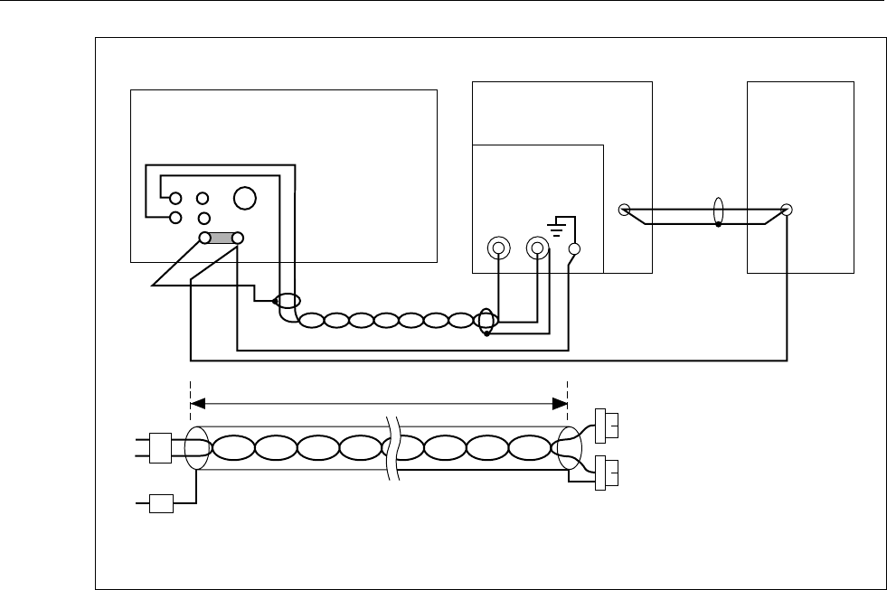
LO
OUTPUT
SENSE
HI
CALIBRATOR
(UUT)
GRD
GND
SHIELDED
TWISTED PAIR
OUTPUT
COAX
TRUE RMS
VOLTMETER
VERTICAL
OSCILLOSCOPE
MAINFRAME*
7A22
PLUG-IN
CLIP LEADS
3' APPROX
GR BANANA PLUGS
SHIELDED TWISTED PAIR CABLE DETAIL
BNC
OSCILLOSCOPE AND AC DIFFERENTIAL
VOLTMETER SHOULD BE ISOLATED FROM
THE POWER LINE GROUND.
*
F3-15.EPS
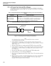
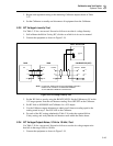
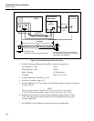
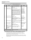
Figure 3-19. DC Voltage Output Noise Test Setup
2. Set the Oscilloscope Differential Amplifier controls as shown below.
Low Frequency -3 dB
High Frequency -3 dB
Input Coupling
Volts/Div
10 Hz
10 kHz
AC (both inputs)
50 µV (Var. to Cal.)
3. Set the Oscilloscope Time/Div for 2 ms.
4. Set the rms voltmeter range to 1V.
5. Set the Calibrator to 2.2V dc, operate. Verify that the reading on the rms voltmeter is
less than 150 mV.
NOTE
This test assumes that the amplifier plug-in and scope have a gain equal
to 0.5V divided by the input/div. setting, which in the above case is 1x10
4
.
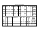
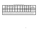
6. Repeat the above process for the remaining tabulated settings shown in Table
3-49; verify that the rms meter indicates less than the amount shown for each
required output level.
7. Press RESET on the Calibrator and disconnect the test configuration.